Novel environmentally-friendly coating device

An environmentally friendly coating, a new type of technology, used in transportation and packaging, dissolving, mixers, etc., can solve problems such as operator injury, poor mixing uniformity, and safety hazards, and achieve the effect of increasing safety and increasing operational stability.

Inactive Publication Date: 2018-08-28
韦健敏
View PDF3 Cites 0 Cited by
  • Summary
  • Abstract
  • Description
  • Claims
  • Application Information

AI Technical Summary

Problems solved by technology

[0002] In some environmentally friendly paint processing and production, it is often necessary to add reagents to some liquid paints for mixing and stirring to achieve dilution. Traditionally, liquid paints are mixed and stirred by stirring devices, but the stirring uniformity is poor, and it is difficult to meet the requirements of processing and production. It is necessary to use the high-speed rotation of the mixer to realize the rapid fusion of liquid paint and reagents. However, since the mixer is often running at high speed when it is working, once it is misoperated, it will cause greater damage to the operator. injury, there is a great potential safety hazard

Method used


Image

  • Novel environmentally-friendly coating device
  • Novel environmentally-friendly coating device
  • Novel environmentally-friendly coating device

Examples


Embodiment Construction

[0018] All features disclosed in this specification, or steps in all methods or processes disclosed, may be combined in any manner, except for mutually exclusive features and / or steps.

[0019] Any feature disclosed in this specification (including any appended claims, abstract and drawings), unless expressly stated otherwise, may be replaced by alternative features which are equivalent or serve a similar purpose. That is, unless expressly stated otherwise, each feature is one example only of a series of equivalent or similar features.

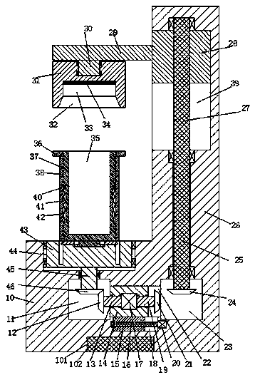
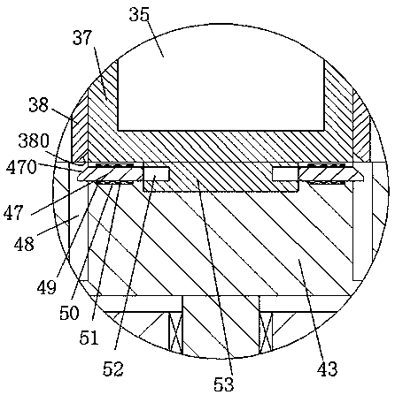
[0020] Such as Figure 1-4As shown, a new type of environmentally friendly coating device of the present invention includes a support base 10, a vertical stand 26 fixedly installed on the right side of the upper end surface of the support base 10 and extending upward, and the end surface of the bottom end of the support base 10 is equipped with a A heavy tank 101, the counterweight 102 is fixed in the counterweight tank 101, the first rotary ...


PUM


Abstract

The invention discloses a novel environmentally-friendly coating device. The device comprises a bearing seat and a vertical frame, wherein the vertical frame is fixedly arranged at the right side of the upper end face of the bearing seat and extends upward, a counterweight groove is formed in the end face of the bottom of the bearing seat, a counterweight block is arranged in the counterweight groove, a first rotating bin and a second rotating bin are arranged in the bearing seat above the counterweight block, a communicated first sliding cavity is formed between the first rotating bin and thesecond rotating bin, a third rotating bin with an upward opening is arranged in the upper end face of the bearing seat and located above the first rotating bin, a rotating table is rotationally arranged in the third rotating bin through a bearing, a first rotating rod is fixedly arranged at the center of the bottom end face of the rotating table, the lower end of the first rotating rod penetratesthrough the bottom wall of the third rotating bin downward, stretches into the first rotating bin and is fixedly provided with a first cone helical wheel, the first rotating rod is rotationally matched with the third rotating bin, a first sliding plate is laterally and movably arranged in a first sliding cavity, a first motor is fixedly arranged in the first sliding plate, and the left and rightsides of the first motor are dynamically connected with a second rotating rod and a third rotating rod which penetrate through the first sliding plate.

Description

technical field [0001] The invention relates to the technical field of environmental protection coatings, in particular to a novel environmental protection coating device. Background technique [0002] In some environmentally friendly paint processing and production, it is often necessary to add reagents to some liquid paints for mixing and stirring to achieve dilution. Traditionally, liquid paints are mixed and stirred by stirring devices, but the stirring uniformity is poor, and it is difficult to meet the requirements of processing and production. It is necessary to use the high-speed rotation of the mixer to realize the rapid fusion of liquid paint and reagents. However, since the mixer is often running at high speed when it is working, once it is misoperated, it will cause greater damage to the operator. Injury, there is a great security risk. Contents of the invention [0003] Aiming at the deficiencies of the above-mentioned technologies, the present invention pr...

Claims


Application Information

Patent Timeline
Patent Type & Authority Applications(China)
IPC IPC(8): B01F9/10B01F15/00
CPCB01F29/30B01F29/80B01F35/453B01F2101/30
Inventor 练酉均
Owner 韦健敏
Why Eureka
Try Eureka