
Pin load measurement method and device, measuring instrument and storage medium

A measurement method and technology of nail loading, applied in the field of testing, can solve problems such as difficult to characterize the distribution of nail load, difficult to widely use, difficult manufacturing process, etc.

Active Publication Date: 2018-08-24
BEIJING AERONAUTIC SCI & TECH RES INST OF COMAC +1
View PDF10 Cites 7 Cited by
  • Summary
  • Abstract
  • Description
  • Claims
  • Application Information

AI Technical Summary

Problems solved by technology

However, the matching state of the metal rod and the nail hole has changed after slotting, which makes it difficult to characterize the specific distribution of the actual structure in the obtained nail load distribution; in addition, the metal groove in the metal rod weakens the bearing capacity of the sensor rod, making the sensor only It can be used under low-load conditions, which limits the application range of the sensor. At the same time, due to the difficulty of the manufacturing process, the manufacturing cost is relatively expensive and difficult to be widely used.

Method used


Image

  • Pin load measurement method and device, measuring instrument and storage medium
  • Pin load measurement method and device, measuring instrument and storage medium
  • Pin load measurement method and device, measuring instrument and storage medium

Examples


Embodiment 1

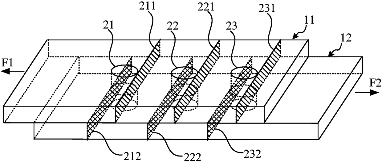
[0032] The composite material connector detected in the embodiment of the present invention includes at least two composite material connecting plates with the same thickness and the same material, each connecting plate is placed in parallel, and adjacent connecting plates are connected by two or more pairs of connecting holes. The hole diameters of the connecting holes are the same. Figure 1A An exemplary three-dimensional structure schematic diagram of a composite material connector is given, which includes two composite material connecting plates 11 and 12 with the same thickness and the same material, wherein the connecting plate 11 and the connecting plate 12 are placed in parallel , and exemplarily gives the situation that two connecting plates are mechanically connected through three pairs of connecting holes—the pair of connecting holes 21 , the pair of connecting holes 22 and the pair of connecting holes 23 . in, Figure 1B for Figure 1A Front view of the connector ...

Embodiment 2

[0053] image 3 It is a schematic flow chart of a nail load measurement method in Embodiment 2 of the present invention. On the basis of the technical solutions of the above-mentioned embodiments, this embodiment further refines the features to improve the technology of the nail load measurement method Program. The method specifically includes:

[0054] S210. When no load is applied to the connecting piece, obtain the three-dimensional position coordinates of the section of the connecting piece tangent to the side walls of each pair of connecting holes to obtain an initial position parameter.

[0055] Further, the step "acquire the cross-section corresponding to the extruded side walls of each pair of connecting holes in the connecting piece when applying loads with opposite directions and the same magnitude to adjacent connecting plates in a direction parallel to the connecting plates The three-dimensional position coordinates of each projection line on the first surface of...

Embodiment 3

[0077] Figure 4 A schematic structural diagram of a nail load measuring device in Embodiment 3 of the present invention, this embodiment is applicable to Figure 1A When the connecting holes in the same or similar connecting pieces of the composite material connecting piece shown in are mechanically connected, the nail load distribution of each pair of connecting holes is measured. The device includes: a first acquisition module 310, a second acquisition module 320 , a deformation ratio determination module 330 and a nail loading value determination module 340 .

[0078] Wherein, the first acquiring module 310 is configured to acquire the projection lines of the section tangent to the side walls of each pair of connecting holes in the connecting piece on the first surface of each connecting plate when no load is applied to the connecting piece. The three-dimensional position coordinates obtain the initial position parameters;

[0079] The second acquisition module 320 is use...


PUM


Abstract

The embodiment of the invention discloses a pin load measurement method and device, a measuring instrument and a storage medium. The method includes the following steps: under two circumstances of notapplying a load to a composite material connecting piece and applying a specific load, obtaining three-dimensional position coordinates of each projection line, on a first surface of a connecting plate, of a cross section tangent with side walls of each pair of connecting holes in the connecting piece to obtain initial position parameters and extrusion position parameters; according to the difference values of extrusion position parameters and the initial position parameters of the projection lines corresponding to each pair of connecting holes and the sum of the difference values of the extrusion position parameters and the initial position parameters of the projection lines corresponding to all the connecting holes, determining a deformation ratio of each pair of connecting holes; and according to the deformation ratio and the applied load, obtaining a pin load value of each pair of connecting holes. By adoption of the abovementioned technical scheme, a noncontact mode is adopted todirect measure pin load distribution in the composite material connecting piece, a measuring error is reduced, cost of pin load measurement is reduced, and thus wide-range use is facilitated.

Description

technical field [0001] The embodiments of the present invention relate to the field of testing, and in particular, to a nail loading measurement method, device, measuring instrument and storage medium. Background technique [0002] With the replacement of aircraft, the application of composite materials in aircraft structures has grown steadily, and has been applied to main load-bearing structures such as fuselages and wings. Due to limitations in design, technology, use and maintenance, it is usually necessary to use mechanical connections, especially nail connections, for load transfer. [0003] In the actual application process, due to the significant difference in the nail load distribution of the mechanical connection of the composite material compared to the metal structure, and the special property of the composite material as a brittle material, it is necessary to accurately calculate the The nail load distribution of . Before using the nail load distribution calcu...

Claims


Application Information

Patent Timeline
IPC IPC(8): G01L5/00
CPCG01L5/00
Inventor 秦田亮季少华徐吉峰
Owner BEIJING AERONAUTIC SCI & TECH RES INST OF COMAC
Learn More