
Glue solution saved type pressing device

A saving glue technology, applied in the field of pressing devices, can solve the problems of glue waste, low cleanliness of the working environment, poor glue box effect, etc., to achieve the goal of avoiding glue waste, firm pressing, and uniform force Effect

Active Publication Date: 2018-08-24
郑州华美彩印纸品有限公司
View PDF3 Cites 2 Cited by
  • Summary
  • Abstract
  • Description
  • Claims
  • Application Information

AI Technical Summary

Problems solved by technology

[0004] Based on the above technical problems, the present invention provides a glue-saving pressing device, which solves the technical problems of poor glue box effect, waste of glue and low cleanliness of the working environment in the past.

Method used


Image

  • Glue solution saved type pressing device
  • Glue solution saved type pressing device
  • Glue solution saved type pressing device

Examples


Embodiment 1

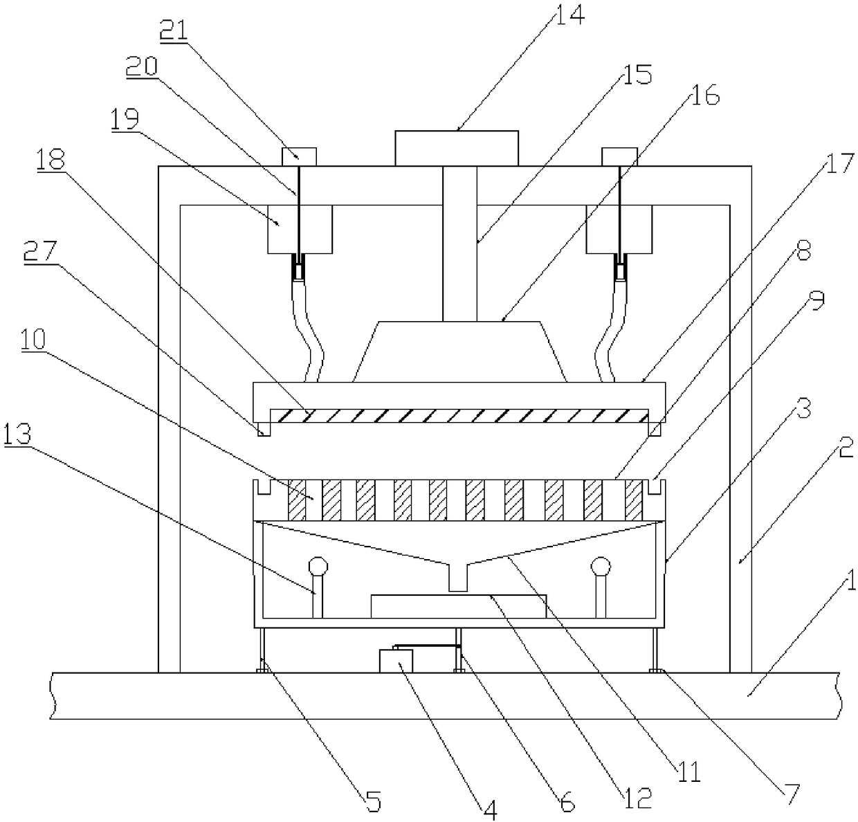
[0026] Such as Figure 1-3 As shown, a glue-saving pressing device includes an operating table 1, and the operating table 1 is provided with a fixed frame 2 and a rotating motor 4,

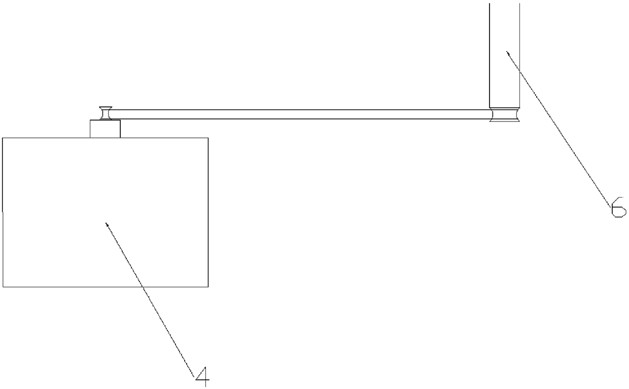
[0027] Described console 1 is provided with four circularly distributed first rotating rods 5, and the upper end of the first rotating rod 5 is provided with support frame 3, and the middle part below support frame 3 is provided with the second rotating rod 6, and the second rotating rod 6 passes through The transmission belt is connected to the output shaft of the rotating motor 4; the bottom ends of the first rotating rod 5 and the second rotating rod 6 are connected to the console 1 through the bearing 7; the top of the support frame 3 is provided with a circular movable pressure plate 8, The outer side of the upper surface of the circular movable pressing plate 8 is provided with a draw-in groove 9 along the circumferential direction of the circular movable pressing plate 8, and the circular m...

Embodiment 2

[0030] Such as figure 1 As shown, the circular fixed platen 17 is connected to the bottom of the first telescopic rod 15 through the buffer plate 16, and the bottom of the circular fixed plate is symmetrically provided with four cards, 27; Below, the inner diameter of the card slot 9 is equal to the outer diameter of the card post 27;

[0031] When this embodiment is used, the circular fixed platen 17 and the circular movable platen 8 are connected together through the clamping column 27 and the clamping groove 9, which can prevent the platen from moving during the pressing process, thereby ensuring the stability of the pressing.

Embodiment 3

[0033] Such as figure 1 As shown, 4-6 heat fans 13 are arranged around the collection tank 12, and the heat fans 13 are located on the support frame 3;

[0034]When the present embodiment is in use, a hot fan 13 is arranged around the liquid outlet funnel 11 to heat the liquid outlet funnel 11 and the circular movable platen 8, so as to prevent excess glue from solidifying and losing fluidity, and cannot enter the collection tank 12 for recycling. ; This structure can ensure the fluidity of the excess glue, thereby ensuring that the excess glue can be recycled from the points.


PUM


Abstract

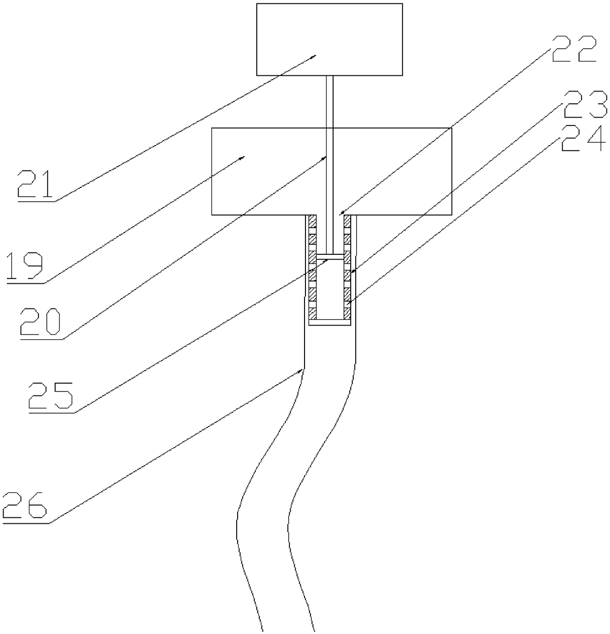
The invention relates to a glue solution saved type pressing device comprising an operation platform. A fixing frame and a rotating motor are arranged on the operation platform. Four first rotating rods are arranged on the operation platform. The upper ends of the first rotating rods are provided with a supporting frame. A second rotating rod is arranged on the lower side of the supporting frame.A movable round pressing plate is arranged on the top of the supporting frame. Clamping grooves are arranged on the upper surface of the movable round pressing plate. The round movable pressing plateis provided with a plurality of solution discharging holes. A solution discharging funnel is arranged at the bottom end of the movable round pressing plate. A first pneumatic cylinder is arranged on the fixing frame and connected with a fixed round pressing plate. A glue infusing plate is arranged on the lower surface of the round fixed pressing plate. Two glue storage bins are symmetrically arranged inside the fixing frame. The lower ends of the liquid storage bins are provided with first glue outlets. The lower ends of the first glue outlets are provided with fixed glue discharging pipes. The fixed glue discharging pipes are provided with a plurality of second glue outlets. The end, sleeved with a glue discharging hose, of each fixed glue discharging pipe is connected with the fixed round pressing plate. The glue solution saved type pressing device is good in box adhesion effect, free of glue solution waste and high in work environment cleanness degree.

Description

technical field [0001] The invention relates to a pressing device, which belongs to the field of printing equipment. More specifically, the invention relates to a glue-saving pressing device. Background technique [0002] The box gluer is a professional glue box made of various materials such as PVC / PET / PP. The operation is simple, light, nimble and flexible, which breaks the traditional method of sticking plastic boxes by hand and the phenomenon of whitening of APET environmental protection plastic boxes when applying glue; this machine can be adjusted according to the size of the plastic box, with high efficiency and fast speed, completely replacing skilled manual gluing way; save a lot of labor and significantly improve efficiency. [0003] However, the existing box gluing machine has inaccurate positioning during the pressing process, poor box gluing effect, waste of glue and excess glue in the pressing process lead to poor cleanliness of the working environment, so tha...

Claims


Application Information

Patent Timeline
Patent Type & Authority Applications(China)
IPC IPC(8): B31B50/62B31B50/64
CPCB31B50/62B31B50/64
Inventor 崔晓明
Owner 郑州华美彩印纸品有限公司
Learn More