
Manipulator joint absolute angle measuring method without encoder

A technology that does not require coding and measurement methods. It is applied in the field of robotics and can solve the problem of measuring the absolute angle of joints in small manipulator joints. It can prevent stalling or lost steps, reduce costs, and ensure continuous rotation.

Active Publication Date: 2018-08-24
SHANGHAI LINGXIAN ROBOTICS TECH CO LTD
View PDF0 Cites 5 Cited by
  • Summary
  • Abstract
  • Description
  • Claims
  • Application Information

AI Technical Summary

Problems solved by technology

[0007] In view of the above-mentioned defects of the prior art, the technical problem to be solved by the present invention is to provide a method for measuring the absolute angle of the manipulator joint without an encoder to solve the existing Technology cannot solve the problem of joint absolute angle measurement in small manipulator joints

Method used


Image

  • Manipulator joint absolute angle measuring method without encoder

Examples


Embodiment 1

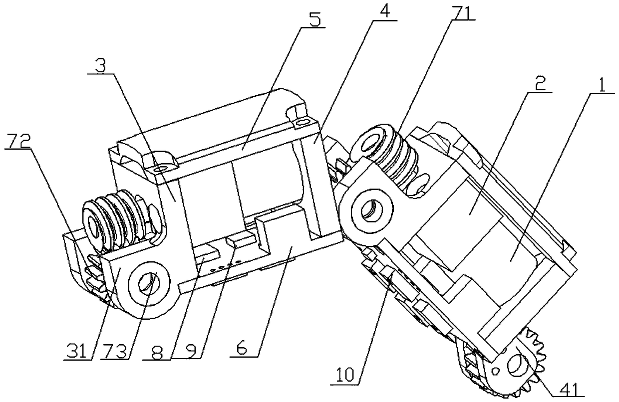
[0040] Based on the linkage structure of the above-mentioned manipulator joints, the method for measuring the absolute angle of the manipulator joints without an encoder for the first time includes the following implementation steps:

[0041] S1: Calibrate the joints of the manipulator, the pressure sensor 10 and the stepping motor 1 used for the first time, and obtain the initial angle value of the joints of the manipulator and the reading of the pressure sensor 10 when the stepping motor 1 is locked;

[0042] S2: Determine the stepping angle of the stepping motor 1, denoted as α;

[0043] S3: The output end of the stepping motor 1 is connected to the input end of the reduction mechanism 2, and the reduction ratio between the stepping motor 1 and the reduction mechanism 2 is determined, which is denoted as k;

[0044] S4: install the worm 71 on the output shaft of the reduction mechanism 2, install the worm / helical gear 72 on the second fixed plate 41 of the joint rear end se...

Embodiment 2

[0055] Based on the linkage structure of the manipulator joints mentioned above, the absolute angle measurement method for the non-encoder-free manipulator joints that is not used for the first time includes the following implementation steps:

[0056] S1: The main control chip 6 initializes the joint angle of the manipulator, that is, reads the relative motion angle value of the manipulator joint when the stepper motor 1 in the fixed address was powered off last time;

[0057] S2: Immediately after the main control chip 6 completes the joint angle initialization, the data in the fixed address is erased, and the main control chip 6 is always in a writable state;

[0058] S3: Calibrate the pressure sensor 10 and the stepping motor 1 to obtain the reading of the pressure sensor 10 when the stepping motor 1 is locked;

[0059] S4: Determine the stepping angle of the stepping motor 1, denoted as α;

[0060] S5: The output end of the stepping motor 1 is connected to the input end ...


PUM


Abstract

The invention discloses a manipulator joint absolute angle measuring method without an encoder. The method comprises the following steps that (1) an initial absolute angle value of a manipulator jointis read; (2) a relative motion angle of the manipulator joint is obtained; and (3) an absolute angle value of the manipulator joint is obtained according to the initial absolute angle value and the relative motion angle. The method has the following beneficial effects that the method cooperates with a software method to realize the absolute angle measurement of the manipulator joint without the encoder, and is suitable for a small manipulator joint structure; the method adopts a stepper motor to drive, so that a stable rotating angle is guaranteed; a worm wheel / inclined gear and worm rod transmission mode is adopted to achieve a self-locking effect; a worm rod only can drive a worm wheel / inclined gear, and the worm wheel / inclined gear cannot drive the worm rod; and when a pressure sensoris adopted to guarantee relative angle recording, continuous rotation of the joint angle is guaranteed, so that the locked rotation or pulse losing problem is prevented, and the cost of the manipulator joint is reduced.

Description

technical field [0001] The invention relates to the field of robots, in particular to a method for measuring the absolute angle of a manipulator joint without an encoder. Background technique [0002] The manipulator is an automatic operation device that can imitate certain movement functions of the human hand and arm to grab, carry objects or operate tools according to a fixed program. It can be programmed to complete various expected operations, with a high degree of accuracy and environmental adaptability. With the development of science and technology, the manipulator has a high degree of flexibility and endurance, and can repeat the same action without fatigue under normal mechanical conditions. The application of manipulator is thus more and more extensive. As the end effector of the robot, the manipulator plays a key role in both industrial robots and service robots. [0003] The manipulator is inseparable from the drive of the manipulator joints during the operati...

Claims


Application Information

Patent Timeline
IPC IPC(8): B25J9/16B25J13/08
CPCB25J9/1694B25J13/088
Inventor 曹俊亮
Owner SHANGHAI LINGXIAN ROBOTICS TECH CO LTD
Learn More