
Automatic power-off device and power-off system with same

An automatic power-off and power supply technology, applied in the direction of circuit devices, battery circuit devices, power devices inside switches, etc., can solve problems such as difficult intelligent terminal battery protection, low working reliability, complex structure of power-off devices, etc., to achieve The effect of automatic physical isolation, high working reliability and simple structure

Pending Publication Date: 2018-08-21
唐宓
View PDF0 Cites 7 Cited by
  • Summary
  • Abstract
  • Description
  • Claims
  • Application Information

AI Technical Summary

Problems solved by technology

[0004] The purpose of the present invention is to provide an automatic power-off device and a power-off system including the automatic power-off device, so as to solve the problem that the existing power-off device has a complex structure, low working reliability, and it is difficult to reliably protect the smart terminal battery. technical issues

Method used


Image

  • Automatic power-off device and power-off system with same
  • Automatic power-off device and power-off system with same
  • Automatic power-off device and power-off system with same

Examples


Embodiment Construction

[0036] The present invention will be described in detail below in conjunction with the accompanying drawings and specific embodiments.

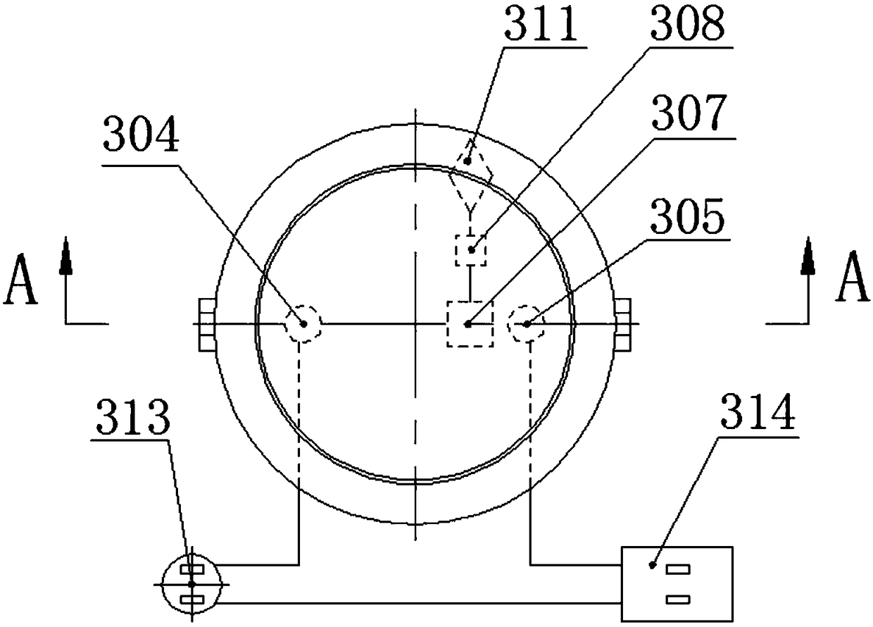
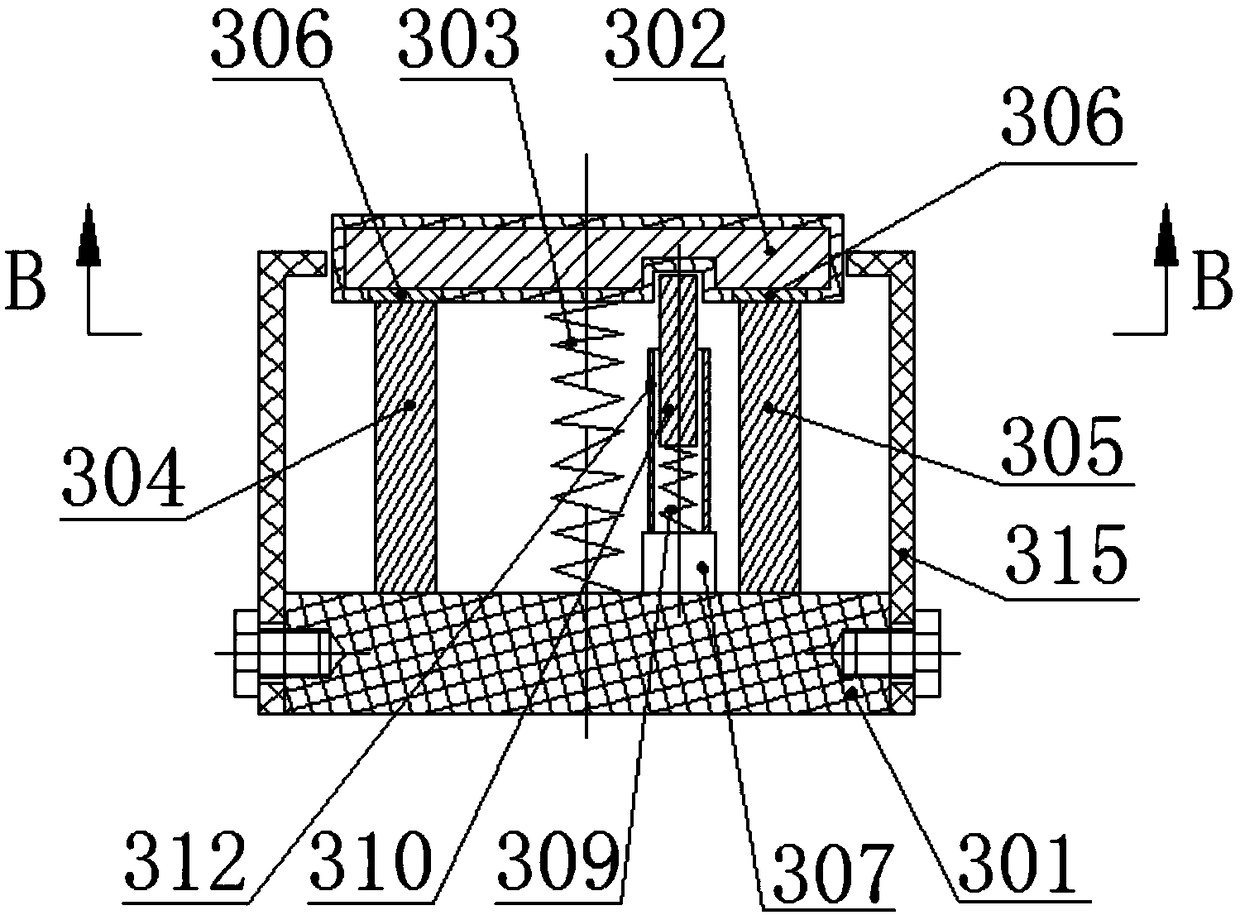
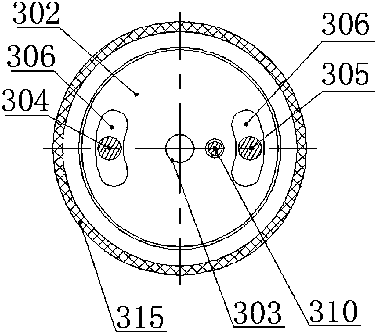
[0037] see Figure 1 to Figure 3 , an automatic power-off device of the present invention, including a base 301, a rotating reset disk 302, a torsion spring 303, a mains input terminal 304, a controllable electric output terminal 305, a sliding conductive sheet 306, an electromagnet 307, and an electromagnet power supply 308 , an elastic member 309 , a positioning pin 310 and a controller 311 . The connection relationship of each component is as follows:

[0038] The base 301 is arranged in parallel with the rotary reset disc 302; a torsion spring 303 is arranged between the base 301 and the rotary reset disc 302, and one end of the torsion spring 303 is fixedly connected with the base 301, and the other end is fixedly connected with the rotary reset disc 302; the base 301 is formed by Made of insulating material, the mains input terminal 3...


PUM


Abstract

The invention belongs to the technical field of intelligent terminal charging control, and relates to an automatic power-off device and a power-off system with the same. The problems are solved that existing power-off devices are complicated in structure and low in work reliability, and batteries of intelligent terminals are difficult to protect reliably. The device is characterized in that a baseand a rotary reset disk are parallel and are fixedly connected to the two ends of a torsion spring respectively; the interior of the rotary reset disk is conductive, the outer surface of the rotary reset disk is insulated, the rotary reset disk is fixedly provided with two sliding conductive sheets which are not in contact with each other, and a current path is formed between the two sliding conductive sheets; a mains input binding post and a controllable power output binding post which are fixedly arranged on the insulating base are matched with the two sliding conductive sheets respectively; the base, an electromagnet, an elastic piece and a positioning bayonet are sequentially and fixedly connected; the rotary reset disk is provided with a positioning hole matched with the positioningbayonet; the electromagnet, an electromagnet power supply and a controller are sequentially connected; the magnetic force of the electromagnet is greater than that of the elastic piece. The inventionfurther discloses the power-off system with the automatic power-off device.

Description

technical field [0001] The invention belongs to the technical field of intelligent terminal charging control, and in particular relates to an automatic power-off device and a power-off system including the automatic power-off device. Background technique [0002] The widespread use of smart terminals such as mobile phones and tablet computers and the emergence of various life-related apps have led to a significant increase in the utilization rate of smart terminals. Therefore, many users arrange the charging time of smart terminals after going to bed at night, and in general, smart terminals The time of connecting with the mains is as long as 8-10 hours. Although the power management module of a general smart terminal has a charging protection function, the power management module is used for charging protection. After the charging is completed, the smart terminal is not physically isolated from the mains. When the power management module fails, the protection will fail. , ...

Claims


Application Information

Patent Timeline
IPC IPC(8): H02J7/00H01H3/28
CPCH02J7/0085H02J7/0031H01H3/28
Inventor 唐宓
Owner 唐宓
Learn More