Variable-frequency resonant withstand voltage and partial discharge test device and method adopting intermittent excitation

A technology of variable frequency resonance withstand voltage and test equipment, which is applied in the direction of testing dielectric strength, etc., can solve the problems of partial discharge signal submersion, observation and detection sensitivity, poor measurement results, etc., and achieve significant economic benefits

Active Publication Date: 2018-08-21
丁晓东
View PDF10 Cites 5 Cited by
  • Summary
  • Abstract
  • Description
  • Claims
  • Application Information

AI Technical Summary

Problems solved by technology

In the past, the partial discharge can be measured synchronously when using the frequency conversion resonant withstand voltage test device for AC withstand voltage, but often due to the interference of the frequency conversion power supply itself and the power supply line, the observation and detection sensitivity of the partial discharge signal of the test system are affected, and the measurement effect is not good. Good, sometimes the partial discharge signal is even submerged by these interference signals, and cannot be observed at all

Method used


Image

  • Variable-frequency resonant withstand voltage and partial discharge test device and method adopting intermittent excitation
  • Variable-frequency resonant withstand voltage and partial discharge test device and method adopting intermittent excitation
  • Variable-frequency resonant withstand voltage and partial discharge test device and method adopting intermittent excitation

Examples


Embodiment Construction

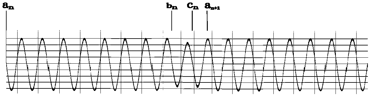
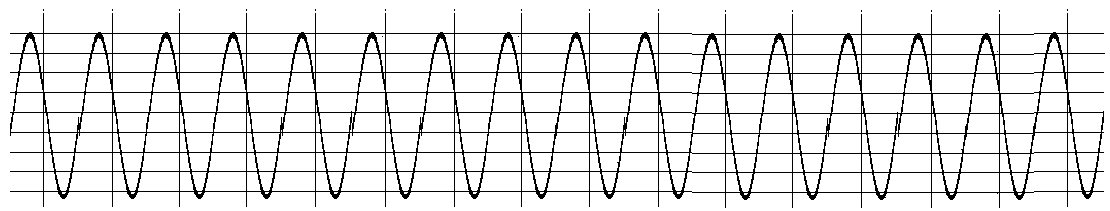
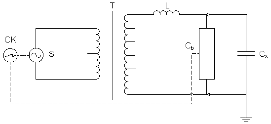
[0016] Example 1 see attached figure 1 The variable frequency resonant voltage withstand partial discharge test device using intermittent excitation is shown, connected to the tested product C X Finally, an AC voltage withstand and partial discharge test system is formed. During the test, by adjusting the output voltage frequency of the variable frequency power supply S, the resonant reactor L and the tested product C X The formed LC circuit reaches the resonance state, and then the tested product C is adjusted by adjusting the output voltage pulse width of the variable frequency power supply S X When the resonant voltage above reaches the set value, the test system enters the state of equal amplitude oscillation (AC withstand voltage). The test voltage waveform is shown in the attached image 3 . At this time, the variable frequency power supply S is programmed to output the excitation voltage intermittently and the output terminal is short-circuited during the intermitten...


PUM


Abstract

The invention discloses a variable-frequency resonant withstand voltage and partial discharge test device and method adopting intermittent excitation, and relates to AC withstand voltage and partial discharge tests of power equipment. The variable-frequency resonant withstand voltage and partial discharge test device comprises a variable-frequency power supply, an excitation transformer, a resonant reactor or a resonant capacitor, a sampling unit, a measurement and control instrument and the like. A test object, which is equivalent to a capacitor or an inductor, is connected when a test is performed so as to form an AC withstand voltage and partial discharge test system, and the test system is enabled to perform partial discharge detection on the test object while being AC voltage withstanding without being influenced by clutter jamming of a power supply line and switching burrs of the variable-frequency power supply in an excitation mode that the variable-frequency power supply intermittently outputs. For a power cable, under an AC withstand voltage test mode in which persistent oscillation, convergent oscillation and divergent oscillation appear alternately in a periodic manner,the variable-frequency resonant withstand voltage and partial discharge test device not only can avoid influences imposed on partial discharge measurement by power supply interference, but also can avoid the possibility of missing detection because the partial discharge cannot be effectively exited due to DC voltage boosting (not an actual working condition) in the traditional damped oscillation wave cable partial discharge test.

Description

technical field [0001] The invention relates to the measurement test of alternating current withstand voltage and partial discharge (hereinafter referred to as partial discharge) of electric power equipment, especially the device and method of the variable frequency resonance withstand voltage partial discharge test using intermittent excitation. Background technique [0002] Before the power line is put into operation or after overhaul, the insulation state of the power components or equipment must be inspected and evaluated, and AC withstand voltage is the most basic test item. The new national electric power test regulations require that high-voltage cables (66kV and above) should be tested for partial discharge at the same time as AC withstand voltage, in order to more comprehensively evaluate the insulation status of cables. In the past, the partial discharge can be measured synchronously when using the frequency conversion resonant withstand voltage test device for AC ...

Claims


Application Information

Patent Timeline
IPC IPC(8): G01R31/12
CPCG01R31/12
Inventor 丁晓东
Owner 丁晓东
Why Eureka
Try Eureka