
Calorimetric reaction container applied to high-precision calorimetric instrument

A reaction vessel and calorimeter technology, which is applied in the field of calorimetric reaction vessels of high-precision calorimeters, can solve problems such as large deviations in scientific research requirements, low measurement accuracy, and poor sealing of bottle mouths, and meet scientific research requirements, Easy to replace and use, and improve the effect of measurement accuracy

Pending Publication Date: 2018-08-21
XIANGNAN UNIV
View PDF6 Cites 2 Cited by
  • Summary
  • Abstract
  • Description
  • Claims
  • Application Information

AI Technical Summary

Problems solved by technology

[0004] But still there are deficiencies in the calorimetric reaction vessel of the calorimeter of prior art, mainly show as: the one, the Dewar bottle that adopts has a part to be single-layer, and bottle mouth is not tightly sealed, and heat insulation, heat preservation The effect is not good; secondly, due to structural limitations, a part of the calorimetric container is exposed outside the constant temperature water tank, which is greatly affected by the environment (air), and a completely constant temperature environment cannot be guaranteed
Therefore, the calorimeter using the calorimetric reaction vessel of the prior art is only a calorimetric device in a semi-adiabatic and semi-constant temperature environment, and cannot prepare a high-precision calorimeter, and the measurement accuracy is not high, and the measurement accuracy cannot be guaranteed. The deviation is large, which is not conducive to cultivating the rigor of students' scientific research

Method used


Image

  • Calorimetric reaction container applied to high-precision calorimetric instrument

Examples


Embodiment Construction

[0028] The present invention is described in detail below in conjunction with accompanying drawing and specific embodiment:

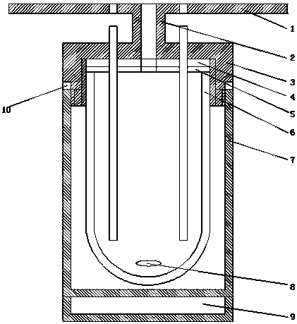
[0029] Such as figure 1 As shown, the calorimetric reaction vessel for high-precision calorimeters of the present invention includes a heat-insulating shell 7, a double-layer silver-plated vacuum Dewar 6, and an "I"-shaped container cover.

[0030] The upper part of the heat insulation shell is open and the lower part is sealed.

[0031] The double-layer silver-plated vacuum Dewar flask is placed in an insulated shell with air insulation between the two. A stirring bar 8 is arranged at the inner bottom of the double-layer silver-plated vacuum Dewar flask.

[0032] The "I"-shaped container cover includes a bracket 1 and a cover 3 . The bracket is located above the cover. The hollow connecting pipe 2 is fixedly connected between the bracket and the cover. The bracket is used to place above the constant temperature water tank of the calorimeter to sea...


PUM


Abstract

The invention discloses a calorimetric reaction container applied to a high-precision calorimetric instrument. The container includes a thermal insulating housing, a double-layer silver-plated vacuumDewar flask and an H-shaped container cover; the upper portion of the thermal insulating housing is opened, and the lower portion of the thermal insulating housing is sealed; the double-layer silver-plated vacuum Dewar flask is placed in the thermal insulating housing, and thermal insulation between the Dewar flask and the housing is achieved through air; a stirrer is arranged at the bottom of theinterior of the double-layer silver-plated vacuum Dewar flask; the H-shaped container cover includes a supporting frame and a cover shield, and the supporting frame is positioned above the cover shield and fixedly connected to the cover shield through a hollow connecting pipe; the supporting frame is used for being placed on a constant-temperature sink opening of the calorimetric instrument to seal a constant-temperature sink of the calorimetric instrument and to fix the thermal insulating housing into the constant-temperature sink of the calorimetric instrument; the cover shield is sealed and fixedly connected with the outer brim of the opening of thermal insulating housing. By adopting the calorimetric reaction container, the calorimetric instrument which is high in measurement precision and capable of ensuring the measurement precision can be manufactured.

Description

technical field [0001] The invention relates to a heat measurement experimental device, in particular to a calorimetric reaction container for a high-precision calorimeter. Background technique [0002] In physical chemistry teaching and scientific experiments, it is often necessary to use a calorimeter to measure the heat emitted by different elements or objects when they burn or dissolve. And the higher the calorimetric accuracy is required, the better. [0003] In order to improve the calorimetric accuracy, most of the existing calorimeters use a Dewar flask as a calorimetric reaction vessel, and the Dewar flask is placed in a constant temperature water tank to ensure that the ambient temperature is as constant as possible. [0004] But still there are deficiencies in the calorimetric reaction vessel of the calorimeter of prior art, mainly show as: the one, the Dewar bottle that adopts has a part to be single-layer, and bottle mouth is not tightly sealed, and heat insula...

Claims


Application Information

Patent Timeline
Patent Type & Authority Applications(China)
IPC IPC(8): G01K17/00
CPCG01K17/00
Inventor 李旭李强国蒋建宏李传华李霞
Owner XIANGNAN UNIV
Learn More