
Multifunctional charging pile

A charging pile and multi-functional technology, applied in the field of multi-functional charging piles, can solve the problems of inconvenient take-up, easy to cause leakage, and reduce the service life of charging piles, so as to avoid electric leakage and electric shock accidents, improve the efficiency of take-up, and improve waterproofing effect of effect

Pending Publication Date: 2018-08-21
LUSHAN COLLEGE OF GUANGXI UNIV OF SCI & TECH
View PDF1 Cites 6 Cited by
  • Summary
  • Abstract
  • Description
  • Claims
  • Application Information

AI Technical Summary

Problems solved by technology

[0003] At present, the commonly used charging piles are generally placed outdoors, and the waterproof effect is not good, which can easily lead to electric leakage and electric shock accidents; when the charging piles are in use, a large amount of heat is generated, and the heat is not dissipated in time, resulting in an increase in internal temperature. A Chinese patent discloses a A heat-dissipating charging pile (authorized notification number CN207241453U), this patented technology can effectively dissipate heat, but it cannot prevent water and external dust from entering the inside of the charging pile, damaging the parts of the charging pile, reducing the service life of the charging pile, and affecting normal use; For the existing charging piles, it is inconvenient to take up the wires, and the winding operation cannot be unified, which leads to poor winding effects, which can easily cause excessive bending of the charging cables and affect the life of the equipment; the current charging piles have single functions and cannot be used for mobile devices. Charging, or can be charged, but there is no place to place the mobile device, making it inconvenient to use

Method used


Image

  • Multifunctional charging pile
  • Multifunctional charging pile
  • Multifunctional charging pile

Examples


Embodiment Construction

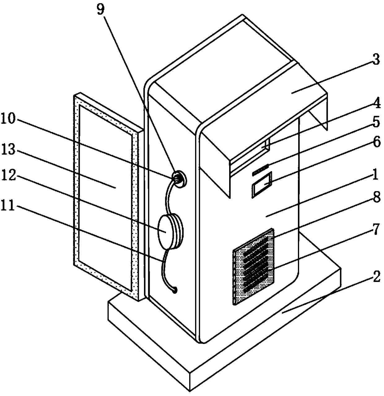
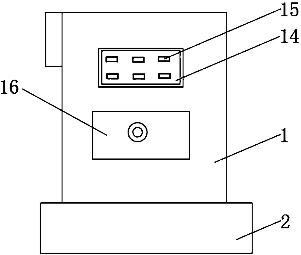
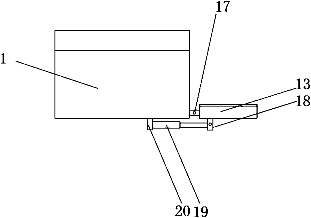
[0027] see Figure 1~5 , in an embodiment of the present invention, a multifunctional charging pile includes a charging pile body 1, a fixing base 2 is provided at the bottom of the charging pile body 1, and a first protective cover 3 is fixedly installed on the upper end of the front surface of the charging pile body 1, A display screen 4 is fixedly installed on the front surface of the charging pile body 1 near the lower position of the first protective cover 3, and a magnetic bayonet 5 is opened on the front surface of the charging pile body 1 near the lower position of the display screen 4, and the charging pile body 1 A control switch 6 is provided on the front surface of the charging pile close to the lower position of the magnetic bayonet 5, and a heat dissipation hole 7 is opened on the front surface of the charging pile body 1 close to the lower position of the control switch 6, and the surface of the heat dissipation hole 7 is covered with a dustproof device 8, and o...


PUM


Abstract

The invention provides a multifunctional charging pile, and belongs to the technical field of charging. The multifunctional charging pile comprises a charging pile body, wherein a fixed seat is arranged at the bottom of the charging pile body; a first protective cover is fixedly mounted at the upper end of the front surface of the charging pipe body; a display screen is fixedly mounted at a position, which is close to a position below the first protective cover, on the front surface of the charging pile body; and a magnetic card port is formed in a position, which is close to a position belowthe display screen, on the front surface of the charging pile body. By the arrangement of the first protective cover, rainwater is prevented from entering the display screen, the magnetic card port and a control switch; by the arrangement of a second protective cover, a charging gun and a wire are protected; in raining, the charging gun is plugged into a charging gun socket; a first antiskid pad achieves an effect of preventing the charging gun from sliding off; an electric telescopic rod pushes the second protective cover; and under the united action of a first connection piece and a second connection piece, a closed space is formed between the second protective cover and the charging pile body; a sealing pad achieves a sealing effect.

Description

technical field [0001] The invention relates to the technical field of charging, in particular to a multifunctional charging pile. Background technique [0002] The function of the charging pile is similar to the refueling machine in the gas station. It can be fixed on the ground or wall, and installed in the parking lot or charging station of public buildings and residential areas. It can charge various types of electric vehicles according to different voltage levels. [0003] At present, the commonly used charging piles are generally placed outdoors, and the waterproof effect is not good, which can easily lead to electric leakage and electric shock accidents; when the charging piles are in use, a large amount of heat is generated, and the heat is not dissipated in time, resulting in an increase in internal temperature. A Chinese patent discloses a A heat-dissipating charging pile (authorized notification number CN207241453U), this patented technology can effectively dissip...

Claims


Application Information

Patent Timeline
IPC IPC(8): B60L11/18G07F15/00H01R13/72H02J7/00
CPCH02J7/0027H01R13/72G07F15/005B60L53/31Y02T90/12Y02T10/70Y02T10/7072
Inventor 覃溪曹乃文龚英姬修子恒
Owner LUSHAN COLLEGE OF GUANGXI UNIV OF SCI & TECH
Learn More