A Scalable Base Station Array Based Optical Tracking Method
An optical tracking and base station technology, applied in the field of optical tracking of base station arrays, can solve problems such as the reduction of the refresh rate of the tracking system, the reduction of the signal sampling rate, and the reduction of the refresh rate of the original signal data, so as to ensure that the tracking accuracy and speed remain unchanged, Tracking range improvement, effect of increasing tracking range
- Summary
- Abstract
- Description
- Claims
- Application Information
AI Technical Summary
Problems solved by technology
Method used
Image

Examples
Embodiment 1
[0075] An embodiment of the present invention provides an optical tracking method based on a scalable base station array, the specific process is as follows Figure 6 As shown, in the embodiment of the present invention, the tracking method is used to track the target to be tracked; the method includes the following steps:
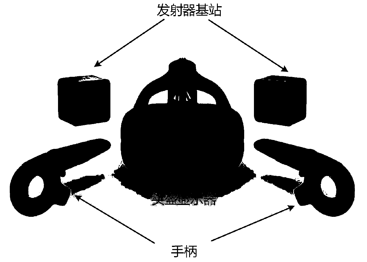
[0076] S1. Set up a receiver on the target to be tracked.
[0077] S2. Using an expandable base station array to scan the target to be tracked.
[0078] The expandable base station array consists of m rows and n columns of m×n base stations, wherein the scanning ranges of adjacent base stations overlap.
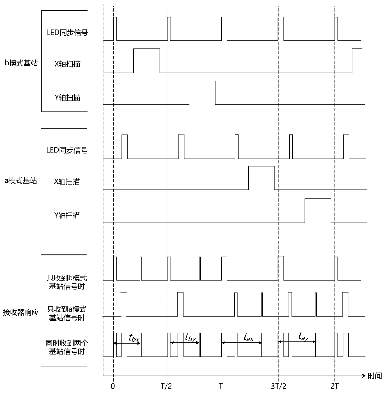
[0079] In the scalable base station array, each row of base stations is composed of class A base stations and class B base stations at intervals.
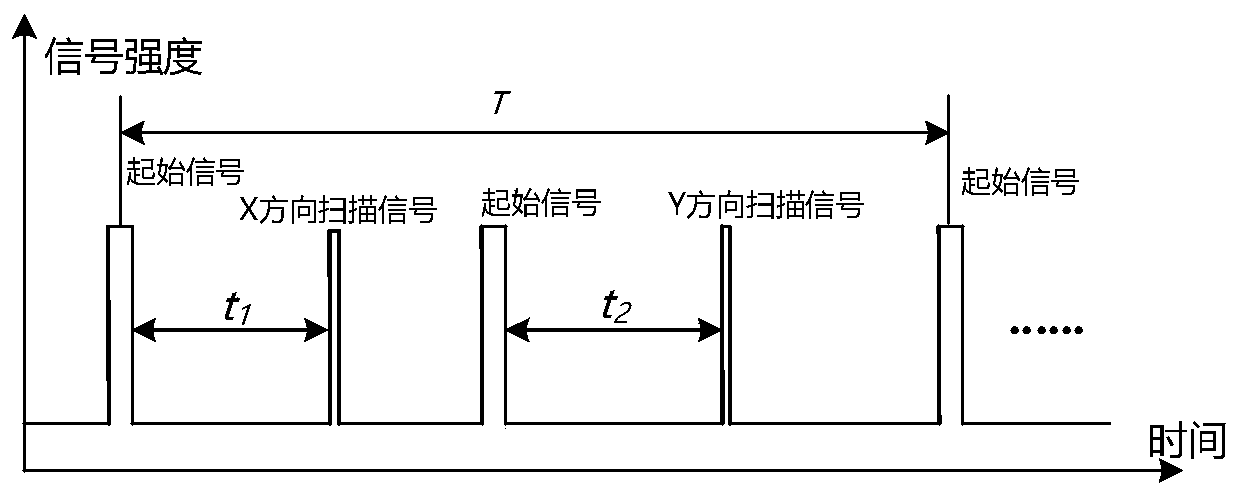
[0080] The duty cycle of the class A base station is set to T A , the duty cycle of class B base station is set to T B , the working time order of the scalable base station array is T A T B T A T B ......
Embodiment 2
[0088] On the basis of Embodiment 1, the embodiment of the present invention adopts a scalable base station array structure such as Figure 8 As shown, the same row of base stations and the same row of base stations in the scalable base station array are all arranged in a straight line;
[0089] Then, each column of base stations is also formed by setting A-type base stations and B-type base stations at intervals.
[0090] In the embodiment of the present invention, S3 is specifically:
[0091] The smallest unit of the base station array is a unit array composed of 2 rows and 2 columns, a total of 4 base stations, where the unit array structure is as follows Figure 9As shown; the scanning area of the cell array is divided into 4 categories, namely the first area, the second area, the third area and the fourth area, Figure 9 1, 2, 3, and 4 are used to mark the first area, the second area, the third area, and the fourth area, respectively.
[0092] The first area is an ar...
Embodiment 3
[0099] The scalable base station array structure adopted in the embodiment of the present invention is as follows Figure 10 As shown, when the base stations in the same row and the base station in the same row are arranged in a straight line, the positions of the base stations are the original positions; the base stations with the number of rows and columns both odd or even are set at the original positions; the number of rows and columns Base stations with different parity are set at the offset set at the bottom right of the original position; the set offset ensures that the scanning ranges of adjacent base stations overlap;
[0100] For the base stations in the scalable base station array, base stations with an odd number of columns are marked as type A, and base stations with an even number of columns are marked as type B.
[0101] in the use of such as Figure 10 When the base station array structure is shown, S3 is specifically:
[0102] The smallest unit of the base s...
PUM
 Abstract
Description
Claims
Application Information
 - R&D
- Intellectual Property
- Life Sciences
- Materials
- Tech Scout
- Unparalleled Data Quality
- Higher Quality Content
- 60% Fewer Hallucinations
Browse by: Latest US Patents, China's latest patents, Technical Efficacy Thesaurus, Application Domain, Technology Topic, Popular Technical Reports.
© 2025 PatSnap. All rights reserved.Legal|Privacy policy|Modern Slavery Act Transparency Statement|Sitemap|About US| Contact US: help@patsnap.com