Equipment for preventing filler in MBBR (Moving Bed Biofilm Reactor) pond from flowing into secondary sedimentation tank

A secondary sedimentation tank and equipment technology, which is applied in sustainable biological treatment, water/sludge/sewage treatment, biological water/sewage treatment, etc., can solve the problem of reducing the biomass of the ecological filter bed and affecting the separation effect of mud and water in the secondary sedimentation tank , blocking the sludge return pump of the secondary sedimentation tank, etc., to achieve the effect of easy installation and disassembly

Inactive Publication Date: 2018-08-17
ANHUI JINDALAI ENVIRONMENT ENG CO LTD
View PDF5 Cites 0 Cited by
  • Summary
  • Abstract
  • Description
  • Claims
  • Application Information

AI Technical Summary

Problems solved by technology

[0005] The purpose of the present invention is to provide equipment that prevents the filler in the MBBR pool from flowing into the secondary sedimentation tank, so as to solve the problem that the filler configured in the MBBR tank will enter the secondary sedimentation tank with the water flow, causing the biomass on the ecological filter bed to decrease, and will block the sewage of the secondary sedimentation tank. Sludge return pump, the problem that affects the separation effect of mud and water in the secondary settling tank

Method used


Image

  • Equipment for preventing filler in MBBR (Moving Bed Biofilm Reactor) pond from flowing into secondary sedimentation tank
  • Equipment for preventing filler in MBBR (Moving Bed Biofilm Reactor) pond from flowing into secondary sedimentation tank
  • Equipment for preventing filler in MBBR (Moving Bed Biofilm Reactor) pond from flowing into secondary sedimentation tank

Examples


Embodiment 1

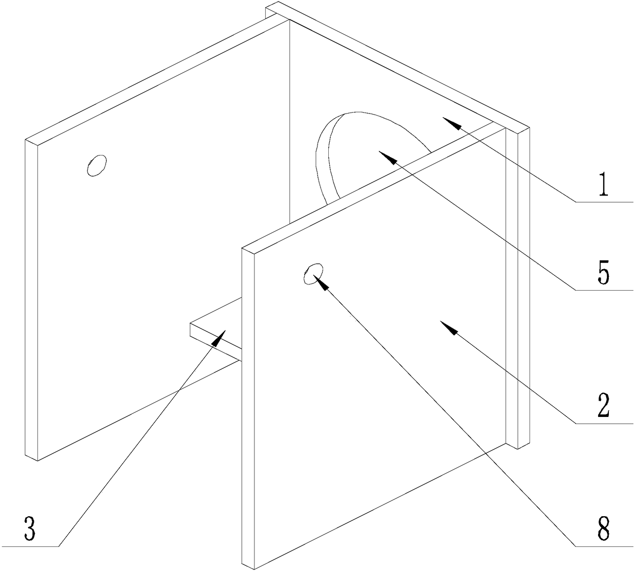
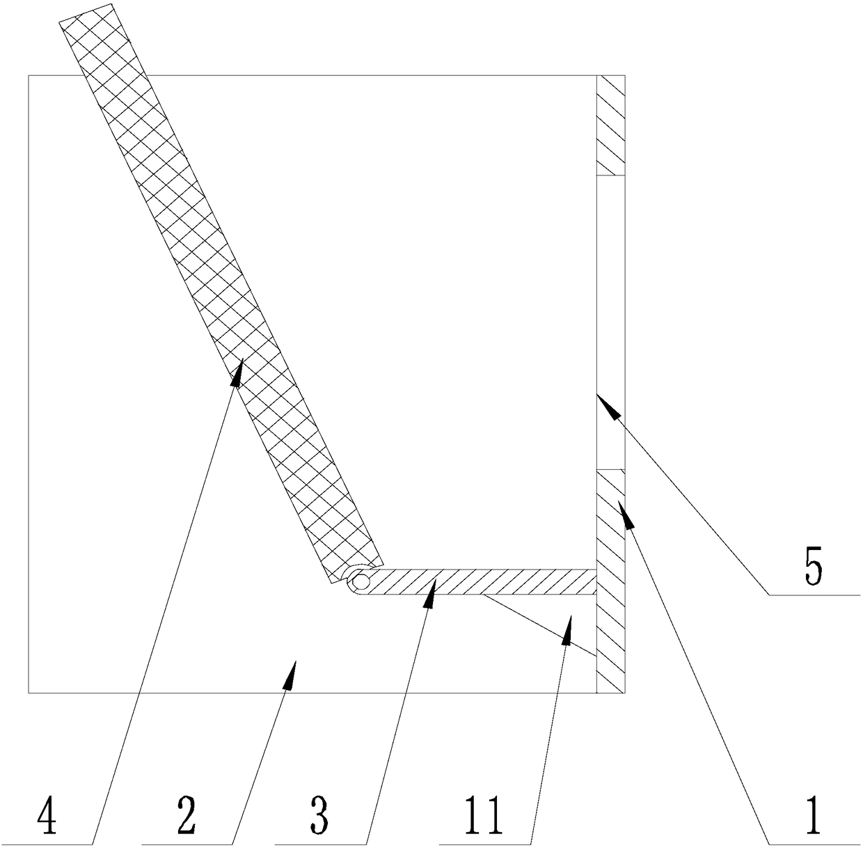
[0030] like Figure 1-Figure 4 As shown, the present invention prevents that the filler in the MBBR tank flows into the equipment of the secondary sedimentation tank, comprising a fixed plate 1, a support plate 2, a connecting plate 3 and an inclined plate 4, and a drain hole 5 is arranged on the plate surface of the fixed plate 1, so that The axis of the drain hole 5 is perpendicular to the fixed plate 1, the support plate 2 has two, and the support plates 2 are parallel to each other and perpendicular to the fixed plate 1, one end of the support plate 2 is connected with the fixed plate 1, and the drain hole 5 , the connecting plate 3 and the inclined plate 4 are all located between the support plates 2, the connecting plate 3 is perpendicular to the fixed plate 1 and the support plate 2 at the same time, one end is connected with the end of the plate surface of the fixed plate 1 near the bottom surface, and the other end is connected with the bottom surface of the fixed plat...


PUM


Abstract

The invention discloses equipment for preventing filler in an MBBR (Moving Bed Biofilm Reactor) pond from flowing into a secondary sedimentation tank. The equipment comprises a fixed plate, support plates, a connecting plate and a sloping plate, wherein a drainage hole is formed in the plate surface of the fixed plate; the axis of the drainage hole is perpendicular to the fixed plate; two supportplates are arranged in parallel and perpendicular to the fixed plate; one end of each of the support plates is connected with the fixed plate; the drainage hole, the connecting plate and the sloping plate are all located between the support plates; the connecting plate is perpendicular to the fixed plate and the support plates at the same time; one end of the connecting plate is connected with oneend which is close to the bottom surface on the plate surface of the fixed plate, and the other end of the connecting plate is hinged to one end of the sloping plate; the hinging axis is perpendicular to the support plates; the sloping plate is a filler filter plate; one end which is far away from a hinging position passes through the space between the support plates; the two ends of the slopingplate are in contact with one support plate respectively. By adopting the equipment, filler is intercepted in the MBBR pond through the sloping plate, so that the filler is prevented from flowing intothe secondary sedimentation pond along with water current, and the growth of living beings on an ecological filter bed and separation of mud and water in the secondary sedimentation pond are facilitated.

Description

technical field [0001] The invention relates to the field of environmental protection, in particular to equipment for preventing fillers in MBBR tanks from flowing into secondary sedimentation tanks. Background technique [0002] During the development of rural industry and aquaculture, the discharge of production and domestic wastewater and fixed waste increased, the lack of management of drinking water sources, the extensive use of chemical fertilizers and pesticides, the random discharge of livestock and poultry manure, and pollutants from township and township enterprises have negatively impacted rural water bodies. The environment has caused huge pollution. [0003] Therefore, it is necessary to treat rural sewage to protect the ecological environment in rural areas and improve livability. [0004] In the MBBR treatment process, the water treated by the MBBR tank needs to be sent to the secondary sedimentation tank with an ecological filter bed for treatment. However,...

Claims


Application Information

Patent Timeline
Patent Type & Authority Applications(China)
IPC IPC(8): C02F3/08C02F3/12C02F3/30
CPCC02F3/087C02F3/1268C02F3/302Y02W10/10
Inventor 涂育伟李飞罗少川程霞风于海宁朱海兵
Owner ANHUI JINDALAI ENVIRONMENT ENG CO LTD
Why Eureka
Try Eureka