Self-positioning tool structure for assembling loop network switchgear cubicle instrument box

A technology for switch cabinets and instrument boxes, which is applied in the field of self-positioning tooling structures, and can solve problems such as large corner deviation, reduced production efficiency, and assembly molding dimensions that cannot meet molding accuracy requirements.

Pending Publication Date: 2018-08-17
SHANGHAI NAJIE COMPLETE SETAB OF ELECTRIC
View PDF0 Cites 2 Cited by
  • Summary
  • Abstract
  • Description
  • Claims
  • Application Information

AI Technical Summary

Problems solved by technology

[0002] Nowadays, the independent instrument box cabinet structure with ring network switchgear on the market usually adopts various side panels, bottom panels, cover panels and mounting beams to assemble bolts and fix structures. When assembling, it needs to be assembled one by one, and the assembly molding size often cannot meet the molding accuracy. Requirements, the diagonal deviation is too large, it is difficult to adjust the molding size, labor and time-consuming; greatly reducing production efficiency

Method used


Image

  • Self-positioning tool structure for assembling loop network switchgear cubicle instrument box
  • Self-positioning tool structure for assembling loop network switchgear cubicle instrument box
  • Self-positioning tool structure for assembling loop network switchgear cubicle instrument box

Examples


Embodiment Construction

[0029] The preferred embodiments of the present invention are given below in conjunction with the accompanying drawings to describe the technical solution of the present invention in detail.

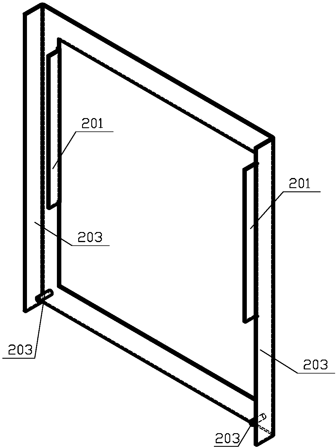
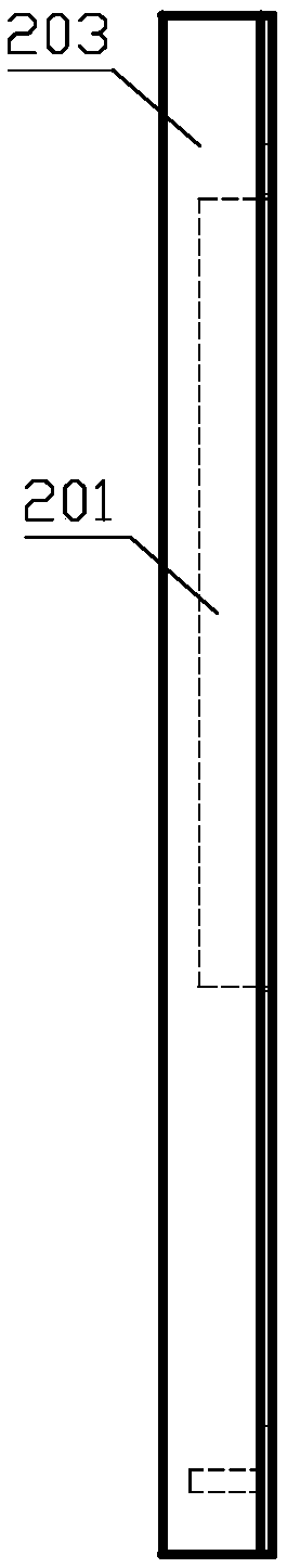
[0030] Figure 15 It is an exploded view of the overall structure schematic diagram of the present invention, Figure 16 It is a schematic diagram after the overall structure of the present invention is assembled, Figure 17 It is a schematic diagram before the left and right side plates are placed for the present invention. Such as Figure 15-17 As shown, the present invention provides a self-positioning tooling structure for the assembly of the meter box of the distribution ring network switchgear, including a positioning base plate 1, a positioning cover plate 2, a positioning rear connecting plate 3, and left and right side plates 4; the positioning base plate 1 is fixed with a positioning Latch 101; positioning cover plate 2 includes positioning flange 201; left and right side pl...


PUM


Abstract

The invention relates to a self-positioning tool structure for assembling a loop network switchgear cubicle instrument box. The tool structure comprises a positioning bottom plate, a positioning coverplate, a positioning rear connecting plate, a left side plate and a right side plate; a positioning bolt is fixed on the positioning bottom plate, the positioning cover plate comprises a positioningfolding edge, the contact part among the left side plate, the right side plate and the positioning bottom plate is provided with an along edge, and a positioning hole is formed in the along edge; andduring installation, the positioning folding edge is folded into the inner frame of the left side plate and the inner frame of the right side plate, during installation, the positioning bolt on the positioning bottom plate is inserted into the positioning hole of the left side plate and the positioning hole of the right side plate, a bent covering edge is bent on the positioning bottom plate, during installation, the left side plate, the right side plate and the positioning rear connecting plate are installed on the inner side of the bent covering edge, during installation, the positioning bolt on the positioning bottom plate is inserted into the positioning hole of the left side plate and the positioning hole of the right side plate, positioning and connecting effects are achieved in thepositioning holes, the folding edge of the positioning cover plate is pressed into the left side plate and the right side plate of the instrument box to ensure the inner forming size of the box body,after the forming precision of the instrument box is guaranteed, the tool structure is disassembled, and after the instrument box is installed, disassembling is carried out.

Description

technical field [0001] The invention relates to a self-positioning tooling structure, in particular to a self-positioning tooling structure for assembling an instrument box of a ring network switchgear comprising a positioning fold and a positioning pin. Background technique [0002] Nowadays, the independent instrument box cabinet structure with ring network switchgear on the market usually adopts various side panels, bottom panels, cover panels and mounting beams to assemble bolts and fix structures. When assembling, it needs to be assembled one by one, and the assembly molding size often cannot meet the molding accuracy. Requirements, the diagonal deviation is too large, it is difficult to adjust the molding size, it is labor-intensive and time-consuming; the production efficiency is greatly reduced. Contents of the invention [0003] In view of the above problems, the main purpose of the present invention is to provide a self-positioning tooling structure for assemblin...

Claims


Application Information

Patent Timeline
Patent Type & Authority Applications(China)
IPC IPC(8): B25B11/02
CPCB25B11/02
Inventor 周文兵朱善勇
Owner SHANGHAI NAJIE COMPLETE SETAB OF ELECTRIC
Why Eureka
Try Eureka