A pulse current assisted micro-punching device and method for a thin metal plate
A pulsed current, metal sheet technology, applied in metal processing equipment, perforation tools, forming tools, etc., can solve the problems of many hole edge defects, short mold service life, large forming force of micro-punching process, etc., to improve production efficiency , The effect of high production efficiency and fast heating speed
- Summary
- Abstract
- Description
- Claims
- Application Information
AI Technical Summary
Problems solved by technology
Method used
Image
Examples
specific Embodiment approach 1
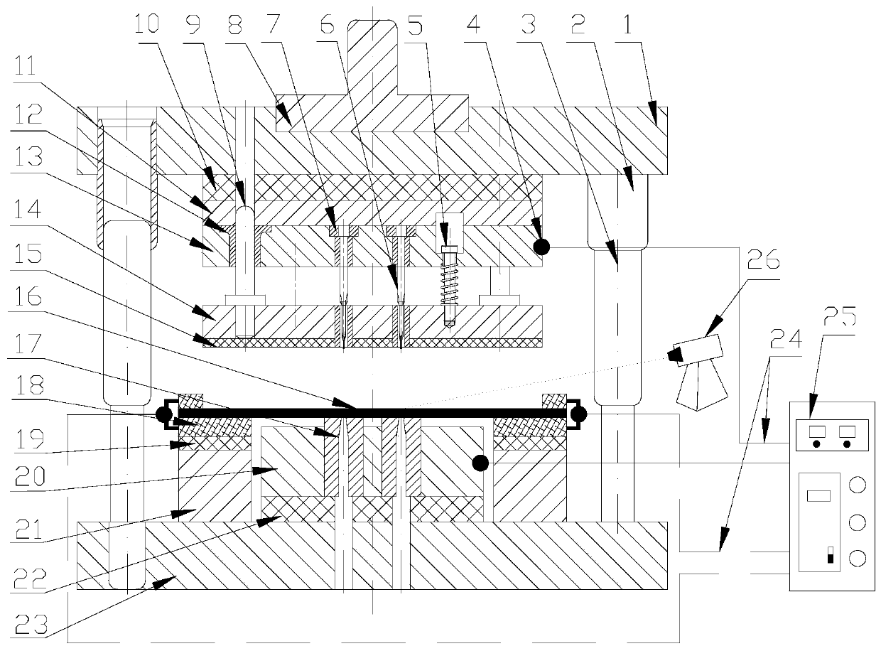
[0034] Specific implementation mode one: combine figure 1 and figure 2 To illustrate this embodiment, a pulse current assisted micro-punching device for a thin metal plate includes a mold assembly and a pulse power supply system; Plate 10, upper backing plate 11, punch fixing plate 13, punch 6, support plate 14, heat insulation plate 15, die 17, die fixing plate 20, lower insulating plate 22 and lower template 23, upper template 1, The upper insulating plate 10, the upper backing plate 11 and the punch fixing plate 13 are connected as one, the die fixing plate 20, the lower insulating plate 22 and the lower template 23 are connected as one, the support plate 14 and the heat insulating plate 15 are connected as one, and the upper A spring 5 is also installed between the backing plate 11, the punch fixing plate 13 and the support plate 14, the die 17 is arranged in the die fixing plate 20, and the upper template 1 and the lower template 23 are arranged on the guide sleeve 1 an...
specific Embodiment approach 2
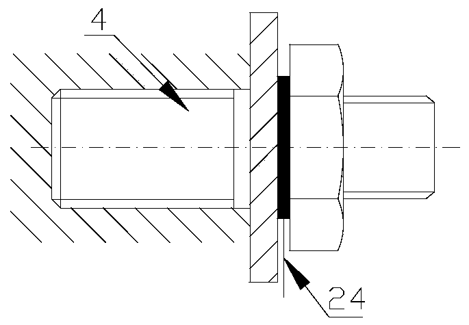
[0036] Specific implementation mode two: combination Figure 1 to Figure 3 Illustrate this embodiment, the pulse power supply system of this embodiment provides the way of energizing the circuit heating blank as follows: the pulse power supply system includes a pulse current generator 28, a power lead 24, an electrode contact device 4 and a pulse current controller 27; the pulse current generator The output end of 28 is connected with the electrode contact device 4 on the punch fixed plate 13 and the die fixed plate 20 through the power lead 24, and the input end of the pulse current generator 28 is connected with the output end of the pulse current controller 27, and the pulse current The controller 27 sends the programmed pulse current parameter signal to the pulse current generator 28, and the pulse current generator 28 outputs a corresponding pulse current according to the received pulse current control signal, and the pulse current passes through the punch fixing plate 13 ...
specific Embodiment approach 3
[0039] Specific implementation mode three: combination Figure 1 to Figure 3 Describe this embodiment, the mode that the pulse power supply system of this embodiment provides energization loop heating billet is: pulse power supply system comprises pulse current generator 28, power lead wire 24, electrode contact device 4 and pulse current controller 27; Die assembly also comprises Two sets of clamping insulation assemblies, each set of clamping insulation assemblies include a blank clamping electrode 18, an insulating gasket 19 and a spacer 21 arranged from top to bottom and connected as a whole; the spacer 21 is installed on the lower insulating plate 22, and the blank 16 is installed on the blank holding electrode 18; the output end of the pulse current generator 28 is connected with the electrode contact device 4 on the two blank holding electrodes 18 through the power lead 24, and the input end of the pulse current generator 28 is connected with the pulse current The outpu...
PUM
| Property | Measurement | Unit |
|---|---|---|
| thickness | aaaaa | aaaaa |
| strength | aaaaa | aaaaa |
Abstract
Description
Claims
Application Information
 - R&D
- Intellectual Property
- Life Sciences
- Materials
- Tech Scout
- Unparalleled Data Quality
- Higher Quality Content
- 60% Fewer Hallucinations
Browse by: Latest US Patents, China's latest patents, Technical Efficacy Thesaurus, Application Domain, Technology Topic, Popular Technical Reports.
© 2025 PatSnap. All rights reserved.Legal|Privacy policy|Modern Slavery Act Transparency Statement|Sitemap|About US| Contact US: help@patsnap.com


