Mist vortex atomizing head

A technology of atomizing head and eddy current, which is applied in the field of atomizing head, can solve the problems of poor atomization effect of atomized gas, achieve improved atomization effect, good diffusion effect, and enhance the effect of fog vortex

Active Publication Date: 2018-08-17
安徽鑫诺医疗设备有限公司
View PDF6 Cites 3 Cited by
  • Summary
  • Abstract
  • Description
  • Claims
  • Application Information

AI Technical Summary

Problems solved by technology

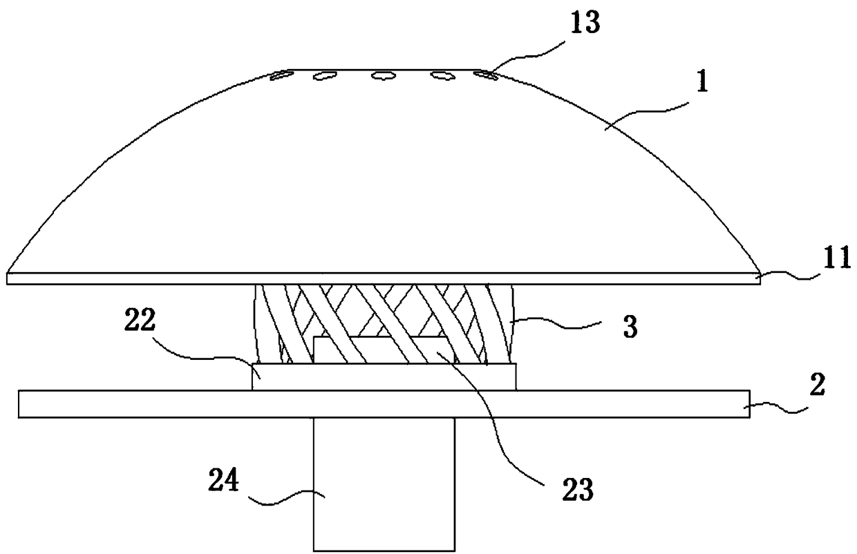
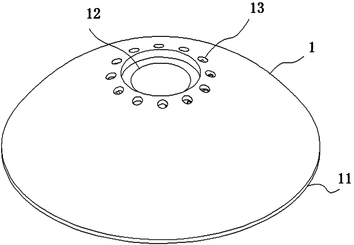
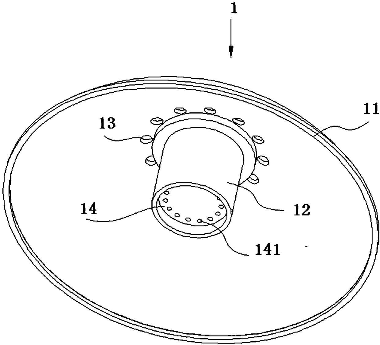
[0004] The purpose of the present invention is to provide a mist vortex atomization head, through which the axial direction of the second through hole provided on the atomization cover points to the center of the sphere where the atomization cover is located and the second through hole and the third through hole are connected through a spiral tube , realize the formation of vortex when the atomizing gas is sprayed out of the atomizing head, and solve the problem of poor atomization effect of the existing atomizing gas

Method used


Image

  • Mist vortex atomizing head
  • Mist vortex atomizing head
  • Mist vortex atomizing head

Examples


Embodiment Construction

[0024] The following will clearly and completely describe the technical solutions in the embodiments of the present invention with reference to the accompanying drawings in the embodiments of the present invention. Obviously, the described embodiments are only some, not all, embodiments of the present invention. Based on the embodiments of the present invention, all other embodiments obtained by persons of ordinary skill in the art without creative efforts fall within the protection scope of the present invention.

[0025] In the description of the present invention, it should be understood that the terms "upper", "lower", "top", "middle", "inner", etc. indicate orientation or positional relationship, and are only for the convenience of describing the present invention and simplifying the description, It is not intended to indicate or imply that the components or elements referred to must have a particular orientation, be constructed and operate in a particular orientation, and...


PUM


Abstract

The invention discloses a mist vortex atomizing head, and relates to the technical field of atomizing heads. The mist vortex atomizing head comprises an arc-shaped cover and a diversion plate. An arc-shaped sealing plate is fixed on one arc-shaped end face of the arc-shaped cover, a first diversion cylinder is arranged at the top of the arc-shaped cover in the diameter direction of a sphere wherethe arc-shaped cover is located, and a plurality of second through holes are uniformly formed in the top of the arc-shaped cover in an annular mode. A flow distribution cylinder is arranged at the center position of one end face of the diversion plate, and third through holes are uniformly formed in a shaft of the flow distribution cylinder in an annular mode. The third through holes communicate with an annular air cavity which is formed in one end face of the diversion plate, and a plurality of fourth through holes are uniformly formed in one end face of the annular air cavity in an annular mode. According to the mist vortex atomizing head, the axial direction of the second through holes formed in an atomizing cover is pointed to the spherical center of the sphere where the atomizing cover is located, the second through holes communicate with the third through holes through spiral pipes, and it is ensured that mist is discharged from the second through holes to form vortexes after passing through the spiral pipes; and the diffusion effect of the mist is better, and the problem that the mist diffuses slowly to condense into large water droplets due to the fact that the diffusion speed is low after discharging is avoided, so that the atomization effect is good.

Description

technical field [0001] The invention belongs to the technical field of atomizing heads, in particular to a mist vortex atomizing head. Background technique [0002] Nebulizers are commonly used in air humidification and treatment of human diseases. The atomizing head is the mist spreading device in the nebulizer. A good atomizing head can better diffuse the atomized liquid in the air or better fully contact with the patient. The structure of the existing atomizing head is relatively simple, and the ability to diffuse the mist in the atomizer is poor and the atomization diffusion effect is not good. [0003] The present invention is dedicated to inventing a mist vortex atomization head, which is used to improve the mist diffusion effect and atomization effect. Contents of the invention [0004] The purpose of the present invention is to provide a mist vortex atomization head, through which the axial direction of the second through hole provided on the atomization cover po...

Claims


Application Information

Patent Timeline
Patent Type & Authority Applications(China)
IPC IPC(8): B05B1/34A61M11/00
CPCA61M2206/16A61M11/006B05B1/3415
Inventor 马志凯马祥龙郭中杰
Owner 安徽鑫诺医疗设备有限公司
Why Eureka
Try Eureka