
Capacitor aging device

A capacitor and sophisticated technology, applied in the field of capacitor aging devices, can solve the problems of unfavorable production efficiency, cumbersome use process of the aging device, low efficiency of the aging device, etc., and achieve the effects of improving applicability, improving processing efficiency, and avoiding false aging.

Active Publication Date: 2018-08-14
ANHUI MASCOTOP ELECTRONICS
View PDF6 Cites 2 Cited by
  • Summary
  • Abstract
  • Description
  • Claims
  • Application Information

AI Technical Summary

Problems solved by technology

[0003] The traditional aging process is DC aging. Using DC power supply, the anode foil of the electrolytic capacitor is clamped by the shrapnel, the negative electrode is connected to the cathode foil of the electrolytic capacitor, and the voltage is gradually increased until it exceeds the rated voltage to reach the set ultimate voltage. Keep the voltage constant until the seasoning is over. The efficiency of the current seasoning device is low. For different types of capacitors, there will be a problem of poor contact between the shrapnel and the positive and negative electrodes, resulting in a false sense of maturity. At the same time, the current seasoning device is cumbersome to use, which is not conducive to improving production efficiency.

Method used

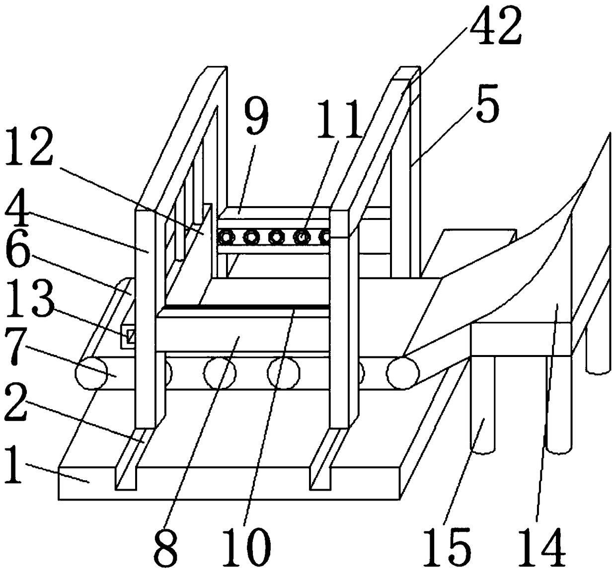

Image

  • Capacitor aging device
  • Capacitor aging device
  • Capacitor aging device

Examples


Embodiment Construction

[0020] The following will clearly and completely describe the technical solutions in the embodiments of the present invention with reference to the accompanying drawings in the embodiments of the present invention. Obviously, the described embodiments are only some, not all, embodiments of the present invention.

[0021] In describing the present invention, it should be understood that the terms "upper", "lower", "front", "rear", "left", "right", "top", "bottom", "inner", " The orientation or positional relationship indicated by "outside", etc. is based on the orientation or positional relationship shown in the drawings, and is only for the convenience of describing the present invention and simplifying the description, rather than indicating or implying that the referred device or element must have a specific orientation, so as to Specific orientation configurations and operations, therefore, are not to be construed as limitations on the invention.

[0022] refer to Figure ...


PUM


Abstract

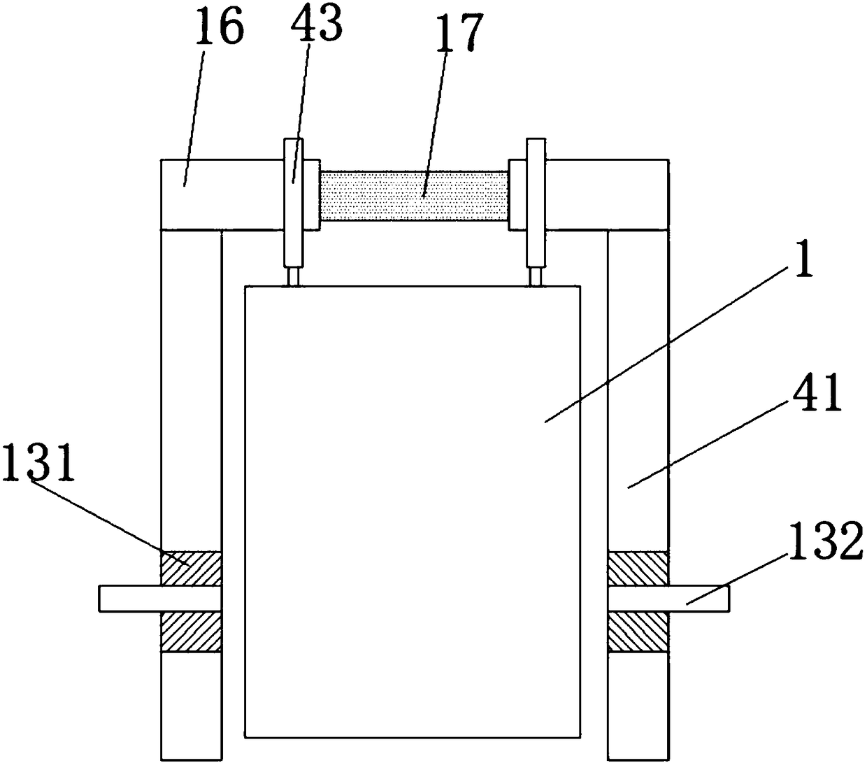
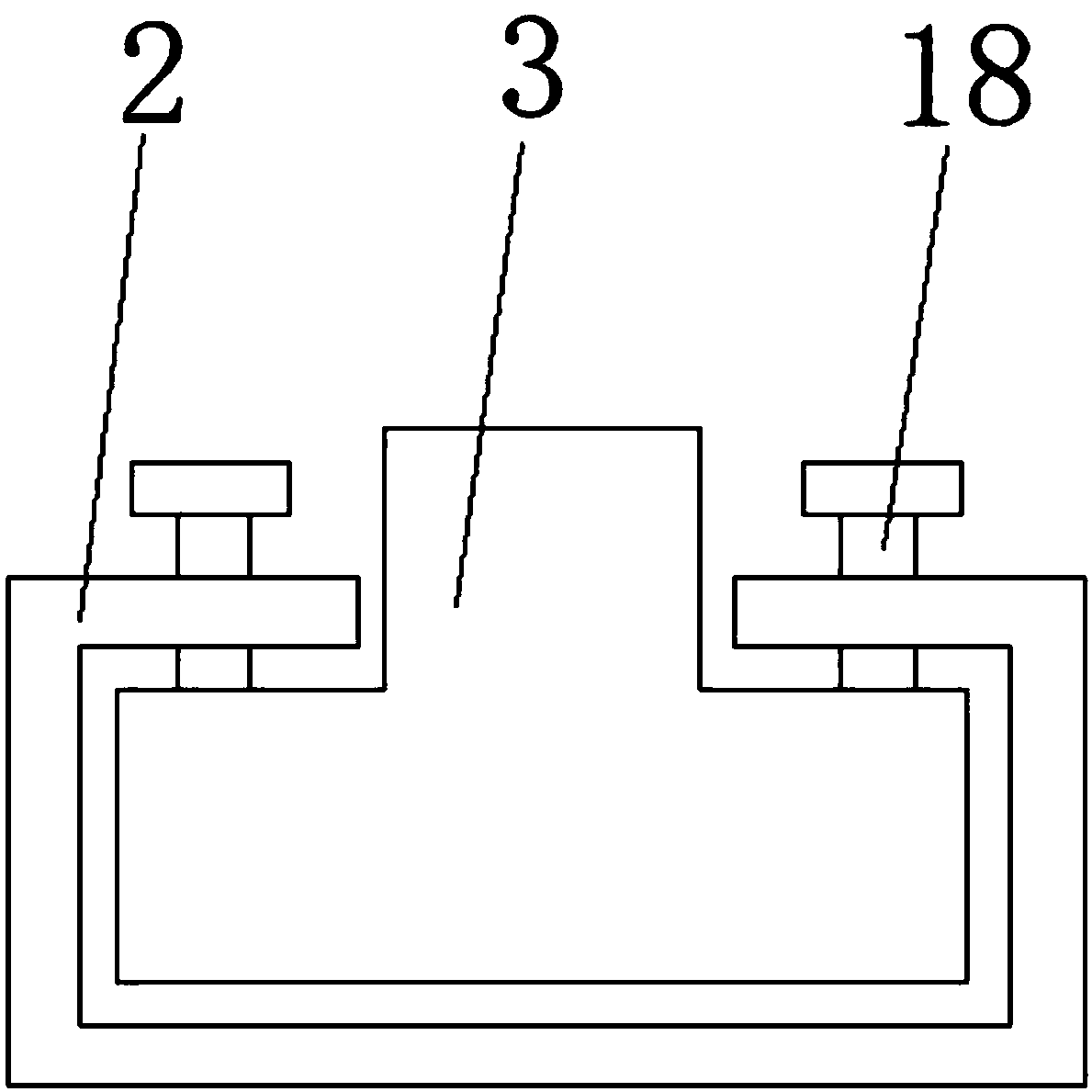
The invention discloses a capacitor aging device. The device comprises a base, two concave sliding chutes in longitudinal symmetric arrangement are formed on the top of the base; two convex sliding blocks are sleeved in the inner wall of each concave sliding chute, the top ends of the convex sliding blocks at the inner wall of the concave sliding chute are fixedly connected with a first frame anda second frame; a horizontal transmission belt is fixedly arranged at the top of the base through a bracket; the transmission belt is in gap junction with each of a first frame and a second frame; theinside wall of the transmission belt is in rotary connection with a transmission assembly; a first clamp plate component and a second clamp plate component in symmetric distribution are orderly connected between the first frame and the second frame along the longitudinal direction; the first clamp plate component directly faces the second clamp plate component, and a first electrode plate is arranged at one side, close to the second clamp plate component, of the first clamp plate component. The capacitor sophisticating device disclosed by the invention is simple in structure and convenient for operation, the false aging problem caused by bad contact is effectively avoided, the automatic arrangement is realized after the feeding, the automatic degree is improved, and the aging efficiency is higher.

Description

technical field [0001] The invention relates to the technical field of electrolytic capacitor production, in particular to a capacitor aging device. Background technique [0002] Sophistication is the last process in the production of electrolytic capacitors and is an essential process. The purpose of aging is to repair the damage of the oxide film on the anode foil as the working medium of the capacitor in the previous process such as slitting, riveting and winding, improve the insulation level and reduce the leakage current. [0003] The traditional aging process is DC aging. Using DC power supply, the anode foil of the electrolytic capacitor is clamped by the shrapnel, and the negative electrode is connected to the cathode foil of the electrolytic capacitor. The voltage is gradually increased until it exceeds the rated voltage, reaching the set final voltage, and Keep the voltage constant until the aging is over. The current aging device is inefficient. For different typ...

Claims


Application Information

Patent Timeline
Patent Type & Authority Applications(China)
IPC IPC(8): H01G13/00H01G11/14
Inventor 杨同彬王军王良国
Owner ANHUI MASCOTOP ELECTRONICS
Learn More