Preparation method of perovskite solar cell module

A technology of solar cell components and solar cells, applied in the field of solar cells, to achieve the effect of high implementation efficiency and satisfying industrial production

Active Publication Date: 2018-08-10
CHANGZHOU UNIV +1
View PDF4 Cites 5 Cited by
  • Summary
  • Abstract
  • Description
  • Claims
  • Application Information

AI Technical Summary

Benefits of technology

This patented technology allows for efficient creation of stable crystal structures called Perovskites (perovskiytes) on both sides of silicon wafers by depositing TiOx onto one side with an organic solvent solution containing hydrogen fluorosilane. After this process, it becomes possible to form isolated lines that connect different parts of each layer together without damaging them during manufacturing processes. Overall, these technical improvements make better use of perpendicularly oriented ferroelectric materials such as lead zirconate-titanates (PZTs).

Problems solved by technology

This patented technical issue addressed by the patents relates to finding ways for producing high efficiency thin film photocells with improved performance on flexible substrate surfaces while also being able to connect them into larger modules efficiently through conventional techniques like scraping away excessive electronic transfer agents from the surface layers during production process.

Method used


Image

  • Preparation method of perovskite solar cell module
  • Preparation method of perovskite solar cell module

Examples


Embodiment Construction

[0022] The present invention is described in further detail now in conjunction with accompanying drawing. These drawings are all simplified schematic diagrams, which only illustrate the basic structure of the present invention in a schematic manner, so they only show the configurations related to the present invention.

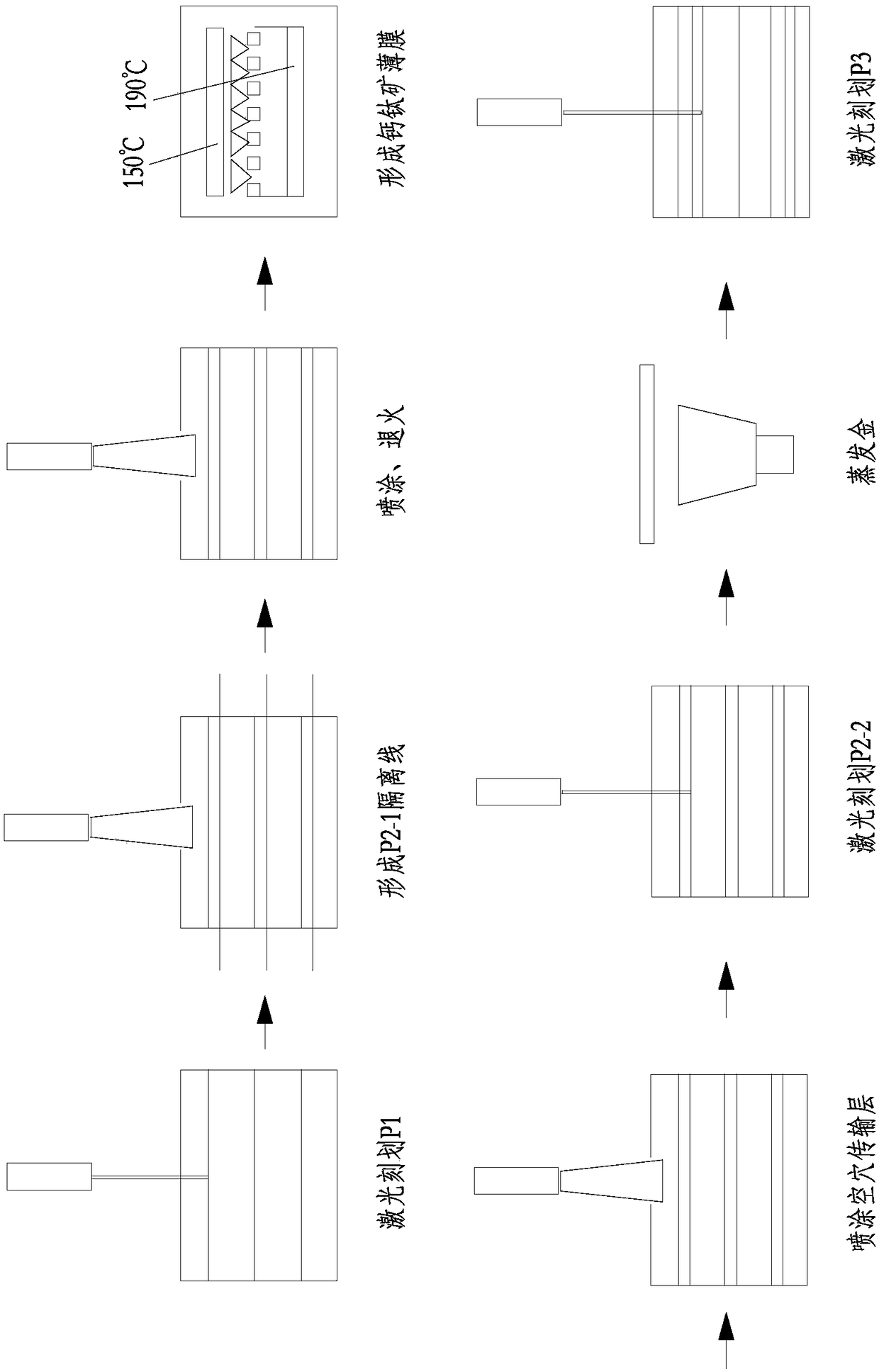
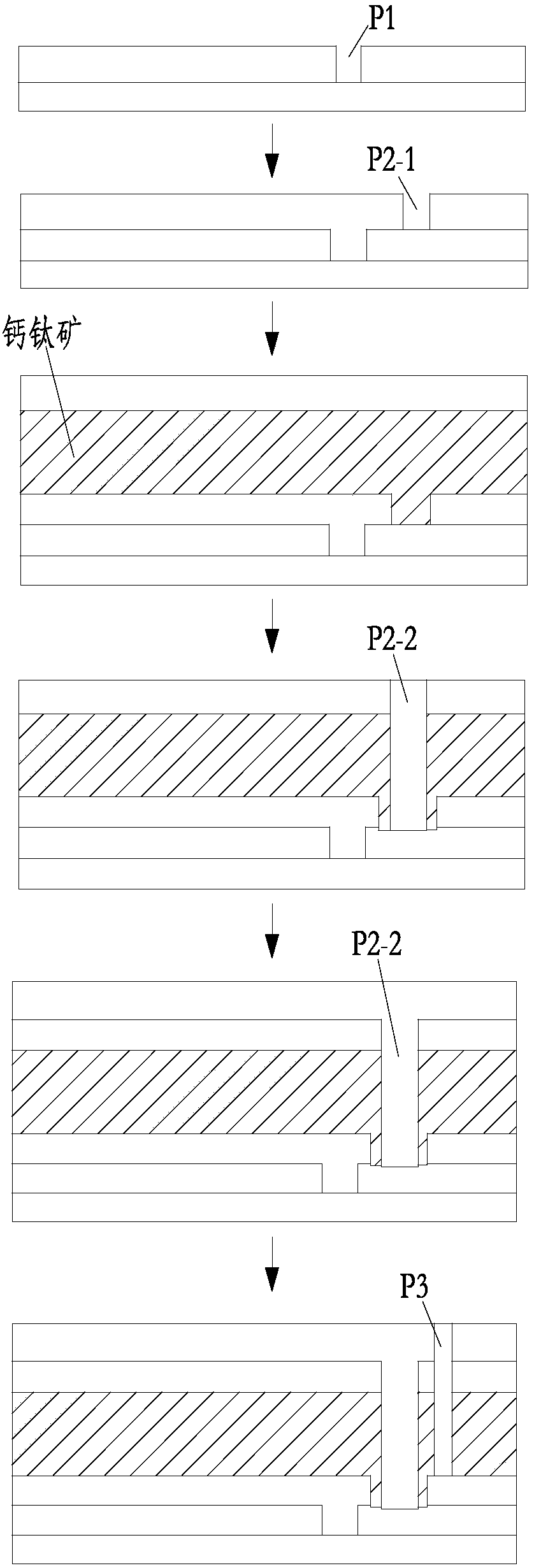
[0023] figure 1 , figure 2 Shown, a kind of preparation method of perovskite solar cell assembly has the following steps:

[0024] a. First, use a 532nm laser to draw the isolation line P1 on the FTO glass. The width of P1 is 100μm, and the distance between P1 is 1cm;

[0025] b. Tighten the scribed FTO glass with a stainless steel wire with a diameter of 100 μm on the upper surface, and stick it closely along the FTO surface. The distance between the stainless steel wire and P1 is 200 μm, and prepare titanium oxide or tin oxide by spray pyrolysis. Thin film with a thickness of 30-50nm, and then remove the stainless steel wire to form a P2-1 isolation line...


PUM

PropertyMeasurementUnit
Diameteraaaaaaaaaa

Abstract

The present invention relates to a preparation method of a perovskite solar cell module. The method comprises the steps of: allowing FTO to scribe a shielding wire P1 with a distance of 1cm by laser;shielding the FTO by a stainless steel wire with a diameter of 100[Mu]m at a position having a 100[Mu]m distance from the P1, employing a thermal spraying method to prepare titanium oxide or tin oxide, removing the stainless steel wire, and forming a shielding wire P2-1; employing a co-evaporation method to prepare a lead iodide/cesium iodide thin film, putting the lead iodide/cesium iodide thin film into a vacuum chamber, heating FAI powder, and performing reaction of FAI steam and the lead iodide/cesium iodide thin film to form a CsxFA1-xPbI3 perovskite thin film; spraying hole transport layer materials, and employing laser to scribe a shielding wire P2-2 along the shielding wire P2-1; and performing thermal evaporation of gold to employ laser to scribe a shielding wire P3 at a positionhaving a 100[Mu]m distance from the P2-2, and performing package to obtain a perovskite solar cell module. The preparation method employs the stainless steel wire to shield the FTO, employs thermal spraying to prepare a titanium oxide/tin oxide thin film and employs the shielding wire P2-1 formed by removal of the stainless steel wire to solve the effective series problem between the perovskite solar cells and improve the implementation efficiency.

Description


Claims


Application Information

Patent Timeline
Owner CHANGZHOU UNIV
Why Eureka
Try Eureka