Illuminating device with separable bulb holder

A lighting device, a separate technology, applied in the direction of portable lighting devices, lighting devices, lighting auxiliary devices, etc., can solve the problems of inability to rotate in multiple directions, increase maintenance costs, manual carrying, etc., to achieve reasonable main structure, reliable principle, Easy to use effects

Pending Publication Date: 2018-08-10
QINGDAO UNIV
View PDF7 Cites 1 Cited by
  • Summary
  • Abstract
  • Description
  • Claims
  • Application Information

AI Technical Summary

Problems solved by technology

[0005] The purpose of the present invention is to overcome the disadvantages of the prior art, aiming at the shortcomings of the existing lighting devices that need to be manually carried during the underground operation, which increases the maintenance cost, and the lamp head and the lamp body of the ordinary lighting device are integrated, and cannot be rotated in multiple directions. , Difficult to stretch and other deficiencies, under the condition of ensuring the convenience of maintenance personnel such as underground pipelines, a detachable lamp head lighting device is designed

Method used


Image

  • Illuminating device with separable bulb holder
  • Illuminating device with separable bulb holder
  • Illuminating device with separable bulb holder

Examples


Embodiment 1

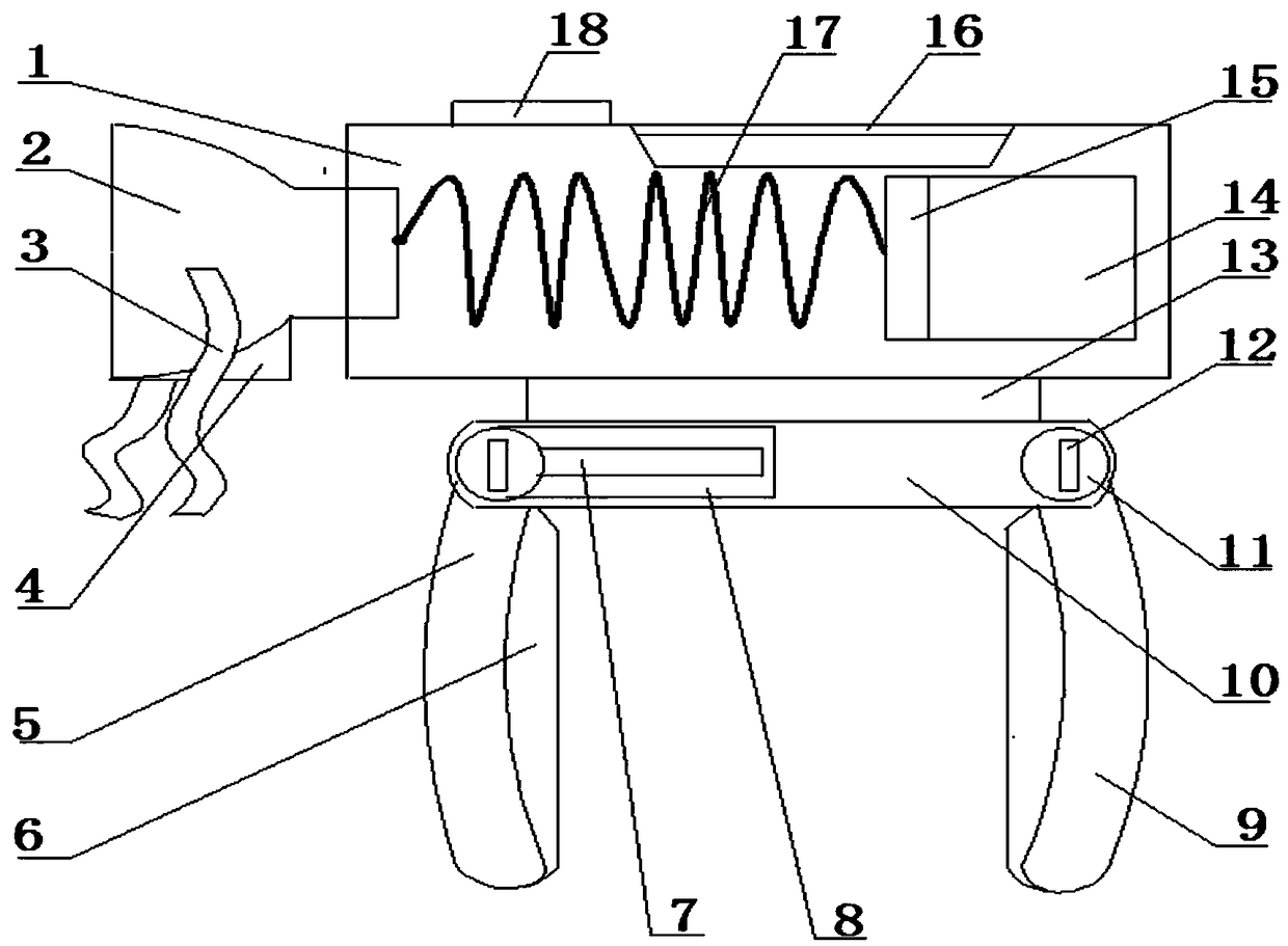
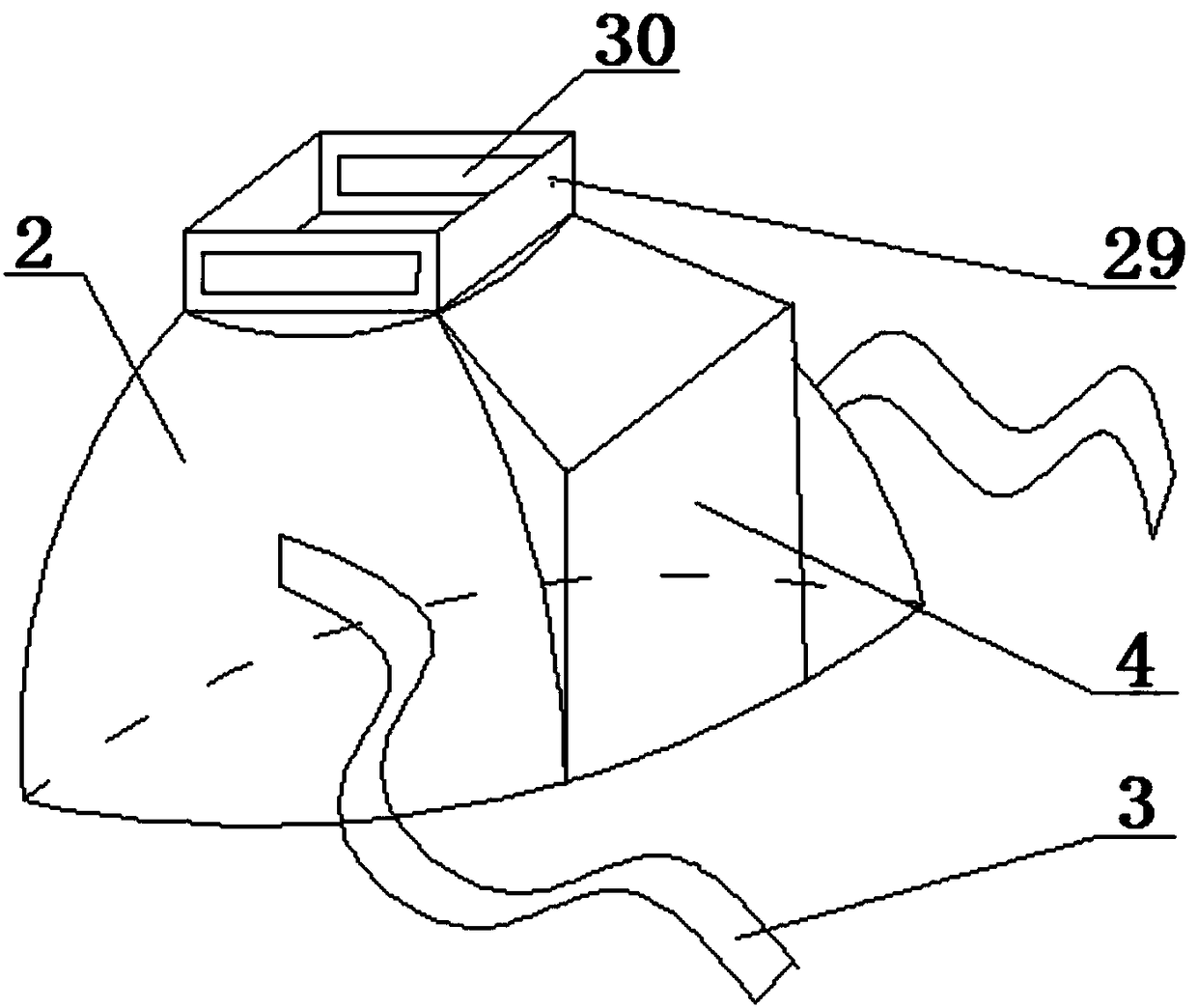
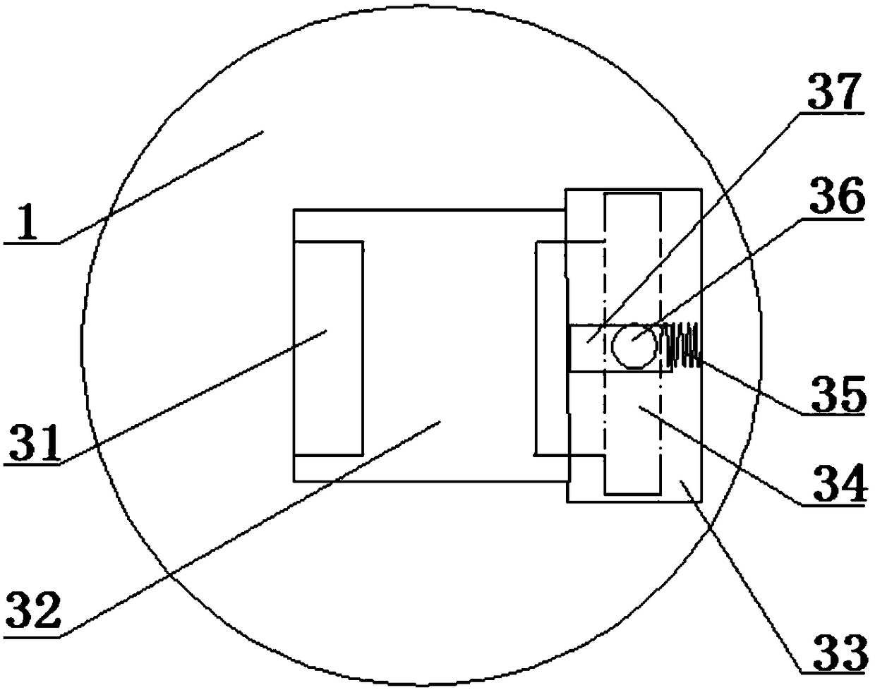
[0020]The detachable lamp head lighting device involved in this embodiment has a main structure including a lamp body 1, a lamp cap 2, a fixing belt 3, a lamp cap seat 4, a front bracket 5, an elastic pad 6, a shaft hole 7, an adjustment slot 8, and a rear bracket 9 , bracket seat 10, adjustment button 11, adjustment rod 12, rotating shaft 13, power supply 14, controller 15, handle 16, metal snakeskin tube 17, adjusting disc 18, card slot seat 29, card slot hole 30, fixed card Slot plate 31, square hole 32, limit groove 33, movable card slot plate 34, spring 35, control knob 36, button groove 37, left rear support 38, right rear support 39, shoulder support hook 40, hook groove 41 and Bracket slot 42; wherein the lamp cap 2 is a bowl-shaped structure, the two sides of the lamp cap 2 are provided with fixing bands 3, the lower end of the lamp cap 2 is provided with a lamp cap seat 4, and the bottom surface of the lamp cap seat 4 is a smooth square surface, when the lamp cap 2 an...

Embodiment 2

[0023] In this embodiment, the adjustment disk 18 described in Embodiment 1 is further described, as Image 6 As shown, the adjusting disk 18 described in this embodiment is disc-shaped, and its main structure includes a switch knob 19, a zero gear 20, a weak light gear 21, a medium light gear 22 and a strong light gear 23; Gear position 20, low light gear position 21, medium light gear position 22 and strong light gear position 23 are respectively electrically connected to the corresponding terminals of the controller 15, and the switch knob 19 can be rotated counterclockwise to zero gear position 20, low light gear position 21. Four gears of medium light gear 22 and strong light gear 23 , so as to adjust the light intensity of the detachable lamp head lighting device described in Embodiment 1.

[0024] The adjusting disk 18 described in this embodiment may adopt a cuboid structure, such as Figure 7 As shown, its main structure includes switch button 24, zero gear 25, low l...


PUM


Abstract

The invention belongs to the technical field of illuminating equipment, and particularly relates to an illuminating device with a separable bulb holder. The illuminating device mainly comprises a lampbody, the bulb holder, a front bracket, an elastic cushion, a back bracket, a bracket seat, a power supply, a metal flexible conduit, and the like, wherein the front end of the lamp body and the backend of the bulb holder are in slot connection; the tail part of the bulb holder is electrically connected with the power supply through the metal flexible conduit; the metal flexible conduit is placed in the lamp body in a spiral manner; the lower end of the lamp body is rotatably connected with the upper end of the bracket seat; and the front bracket and the back bracket of the bracket seat canbe bucked on human shoulders after being spread. The illuminating device can be fixed to human shoulders, maintenance operation of maintenance personnel is not affected, the bulb holder and the lampbody can be separated, and utilization is convenient; and besides, the bulb holder is connected with the power supply through the metal flexible conduit, the bulb holder can rotate in multiple directions by 360 degrees, the device has flexibility, can better adapt to various complex underground operation environments, and is particularly suitable for small-space operation like underground networkmaintenance, utilization is convenient, and an application environment is friendly.

Description

Technical field: [0001] The invention belongs to the technical field of lighting equipment, and relates to a portable lighting device for underground construction, in particular to a detachable lamp head lighting device, which can be fixed on the shoulder of a human body or placed on an underground construction site for lighting. The lamp head and the lamp body are connected by a card slot, which is flexible and convenient to use, and is suitable for maintenance and construction operations in various underground pipelines or large equipment rooms. Background technique: [0002] With the rapid development of society today, the development and utilization of underground space has become a major trend in urban construction. The development of urban underground space includes the construction of underground projects, such as the construction of underground railways, underground shopping malls, and warehouses, as well as the construction of urban underground pipelines, such as Co...

Claims


Application Information

Patent Timeline
Patent Type & Authority Applications(China)
IPC IPC(8): F21L4/00F21V21/10F21V23/00F21V21/40F21V17/16F21V17/10F21V21/02F21V21/32F21V14/02
CPCF21L4/005F21V14/02F21V17/10F21V17/164F21V21/02F21V21/10F21V21/32F21V21/40F21V23/003
Inventor 于正河赵园坤迟庆东于希萌刘闪闪周末
Owner QINGDAO UNIV
Why Eureka
Try Eureka