An autonomous take-off control system and method for a flapping-wing aircraft

A flapping-wing aircraft and control system technology, applied in the field of flapping-wing aircraft, can solve problems such as involuntary take-off, and achieve the effects of reducing power, improving efficiency, and compact structure

Active Publication Date: 2021-02-19
UNIV OF SCI & TECH BEIJING
View PDF5 Cites 0 Cited by
  • Summary
  • Abstract
  • Description
  • Claims
  • Application Information

AI Technical Summary

Problems solved by technology

[0004] The purpose of the embodiment of the present invention is to solve the problem in the prior art that the flapping-wing aircraft must rely on hand-holding to launch and give initial speed, and proposes an autonomous take-off auxiliary system and autonomous take-off control method of the flapping-wing aircraft, which can get rid of the traditional flapping-wing aircraft take-off Involuntary predicament, use the encoder to carry out precise speed control of the carrier car, use the strain measurement device to measure the force state of the flapping-wing aircraft, and use these data to accurately obtain the state information of the flapping-wing aircraft before take-off, and realize the control of the flapping-wing aircraft. Take off autonomously, so that the flapping wing aircraft can obtain a better flight initial state

Method used


Image

  • An autonomous take-off control system and method for a flapping-wing aircraft
  • An autonomous take-off control system and method for a flapping-wing aircraft
  • An autonomous take-off control system and method for a flapping-wing aircraft

Examples


no. 1 example

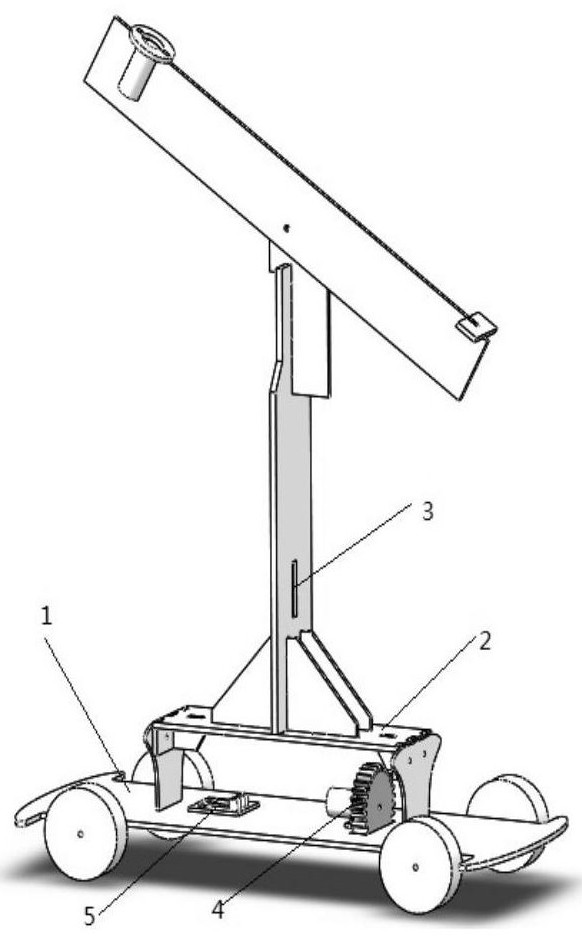
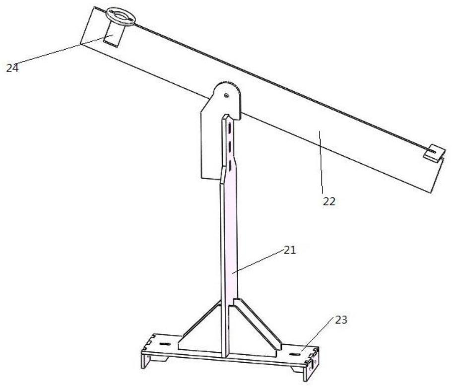
[0064] This embodiment provides an autonomous take-off assisting system for a flapping-wing aircraft, figure 1 It is a structural schematic diagram of the autonomous take-off auxiliary system of the flapping-wing aircraft in this embodiment. Such as figure 1 As shown, the autonomous take-off auxiliary system of the flapping wing aircraft described in this embodiment includes: remote control car 1, support 2, strain measuring device 3, vehicle speed measuring device 4, vehicle-mounted control board 5, airborne control board 6 ( figure 1 not shown in); among them,

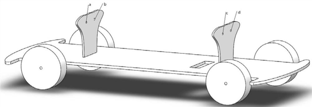
[0065] The remote control car 1 is used to carry a support 2 , a strain measuring device 3 , a vehicle speed measuring device 4 , and a vehicle control panel 5 . figure 2 Shown is a schematic structural diagram of the remote control car described in this embodiment. Such as figure 2 As shown, the remote control car 1 has four installation holes a, b, c, d. In the actual preparation process, the remote control ...

no. 2 example

[0083] This embodiment provides a control system for autonomous take-off of a flapping-wing aircraft, Figure 7 Shown is a schematic structural diagram of the autonomous take-off control system of the flapping-wing aircraft in this embodiment. Such as Figure 7 As shown, the autonomous take-off control system of the flapping-wing aircraft in this embodiment includes the autonomous take-off assisting system of the flapping-wing aircraft in the first embodiment, and also includes: a remote controller, a wireless receiver, the flapping-wing aircraft, and an attitude sensor. The wireless receiver here can be mounted on the remote control car for wireless communication with the remote control. The airborne control board is installed on the flapping-wing aircraft; the attitude sensor is installed on the flapping-wing aircraft.

[0084] Figure 8 Shown is a schematic diagram of the working principle of the autonomous take-off control system of the flapping-wing aircraft in this em...

no. 3 example

[0086] This embodiment provides a control method for autonomous take-off of a flapping-wing aircraft, said method is realized based on the control system for autonomous take-off of the flapping-wing aircraft described in the second embodiment, Figure 9 It is a schematic flow chart of the autonomous take-off control method of the flapping-wing aircraft in this embodiment. Such as Figure 9 As shown, the autonomous take-off control method of the flapping wing aircraft of the present embodiment comprises the following steps:

[0087] Step S1, fix the flapping-wing aircraft on the remote control car, and preset the vehicle speed threshold for autonomous take-off and start of the flapping-wing aircraft.

[0088] Preferably, in this step, fixing the flapping-wing aircraft on the remote control car is further as follows:

[0089] The flapping wing aircraft is fixed on the beam of the remote control car through the magnetism generated by electrifying the electromagnet, and the comm...


PUM


Abstract

The invention provides a flapping-wing aircraft autonomous take-off control system and method. The system includes: a remote control car, a bracket, a strain measurement device, a vehicle speed measurement device, a vehicle control board, and an airborne control board; Accurate control of speed, use the strain measuring device to measure the state of force, and use these data to accurately obtain the state information of the flapping-wing aircraft before take-off, get rid of the predicament that the traditional flapping-wing aircraft needs to be hand-held and involuntary to take off, and realize the autonomous take-off of the flapping-wing aircraft . The invention can obtain a better flying initial state of the flapping-wing aircraft; under a suitable flapping-wing frequency, the power can be reduced and the efficiency can be improved after the combination of the trolley system and the aircraft system. The auxiliary system of the invention is compact in structure, light in weight, easy to carry and easy to install, and is suitable for use in the autonomous take-off control of flapping-wing aircraft.

Description

technical field [0001] The invention belongs to the technical field of flapping-wing aircraft, and in particular relates to an autonomous take-off control system and method of the flapping-wing aircraft. Background technique [0002] In recent years, Flapping-wing aerial vehicles (Flapping-wing aerial vehicles), as a new type of bionic aircraft, are bionic robots manufactured by imitating the flight methods of insects and birds. It has low and significant advantages, and has broad application prospects in national defense, military and civilian fields. However, because the flapping wing aircraft cannot flap its wings and take off in situ like the birds in reality. Through the force analysis of the flapping-wing aircraft, the weight of the aircraft is 10mN greater than the maximum lift it can provide under static conditions, which means that it is difficult for the fuselage to take off directly from a static state on the ground to generate enough lift to achieve flight. Th...

Claims


Application Information

Patent Timeline
Patent Type & Authority Patents(China)
IPC IPC(8): G05D1/10
CPCG05D1/101
Inventor 贺威康业猛冯富森穆新星田淑芬李鸿一孙长银
Owner UNIV OF SCI & TECH BEIJING
Why Eureka
Try Eureka