
Heat dissipation type motor for domestic stirrer

A mixer and heat-dissipating technology, which is applied in the direction of electrical components, electromechanical devices, electric components, etc., can solve the problems that the heat cannot be dissipated quickly and in time, the heat dissipation structure is not ideal, and the heat dissipation performance is not ideal, so as to improve the heat exchange effect and maintain Work performance, the effect of accelerating heat dissipation

Inactive Publication Date: 2018-07-31
湖州正鸣塑胶科技有限公司
View PDF0 Cites 2 Cited by
  • Summary
  • Abstract
  • Description
  • Claims
  • Application Information

AI Technical Summary

Problems solved by technology

For high-speed motors for home appliance mixers, the motor rotor and motor shaft rotate at a high speed, which requires high heat dissipation. Even if a cooling fan is installed in the existing motors for home appliance mixers, the heat dissipation structure is still not ideal. , the heat dissipation speed is lower than the heat generation speed, so that the heat cannot be dissipated quickly and in time, so that the heat accumulates inside the motor, which not only easily leads to the decline of the motor function, affects the use effect, but even burns the internal parts of the motor, reducing the use of the motor life
Therefore, the existing motors for home appliance mixers have the problem of unsatisfactory heat dissipation performance and affecting service life.

Method used


Image

  • Heat dissipation type motor for domestic stirrer
  • Heat dissipation type motor for domestic stirrer
  • Heat dissipation type motor for domestic stirrer

Examples


Embodiment Construction

[0016] The present invention will be further described below in conjunction with the accompanying drawings and embodiments, but not as a basis for limiting the present invention.

[0017] Example.

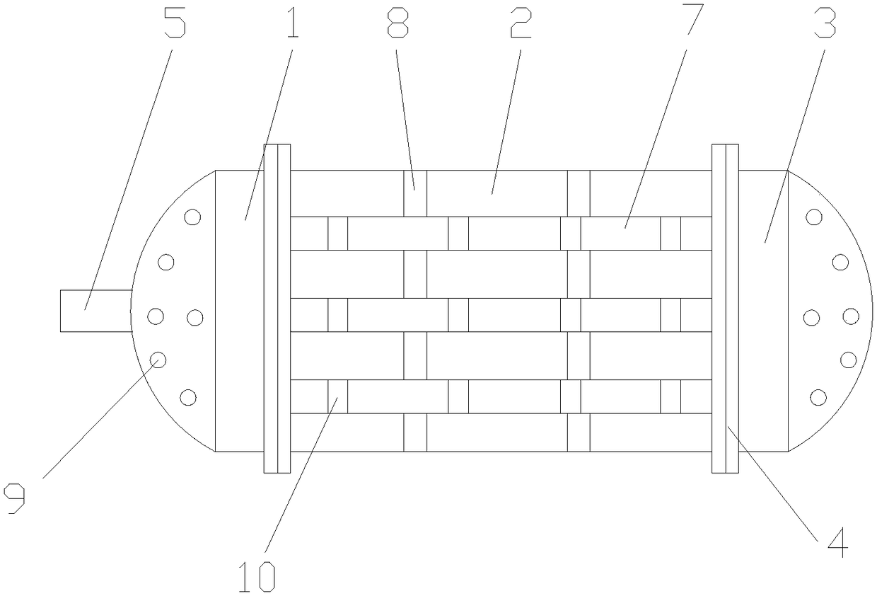
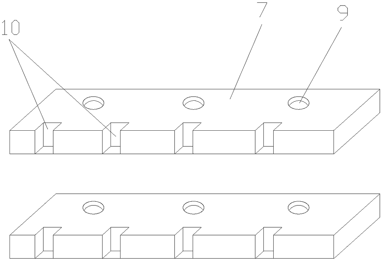
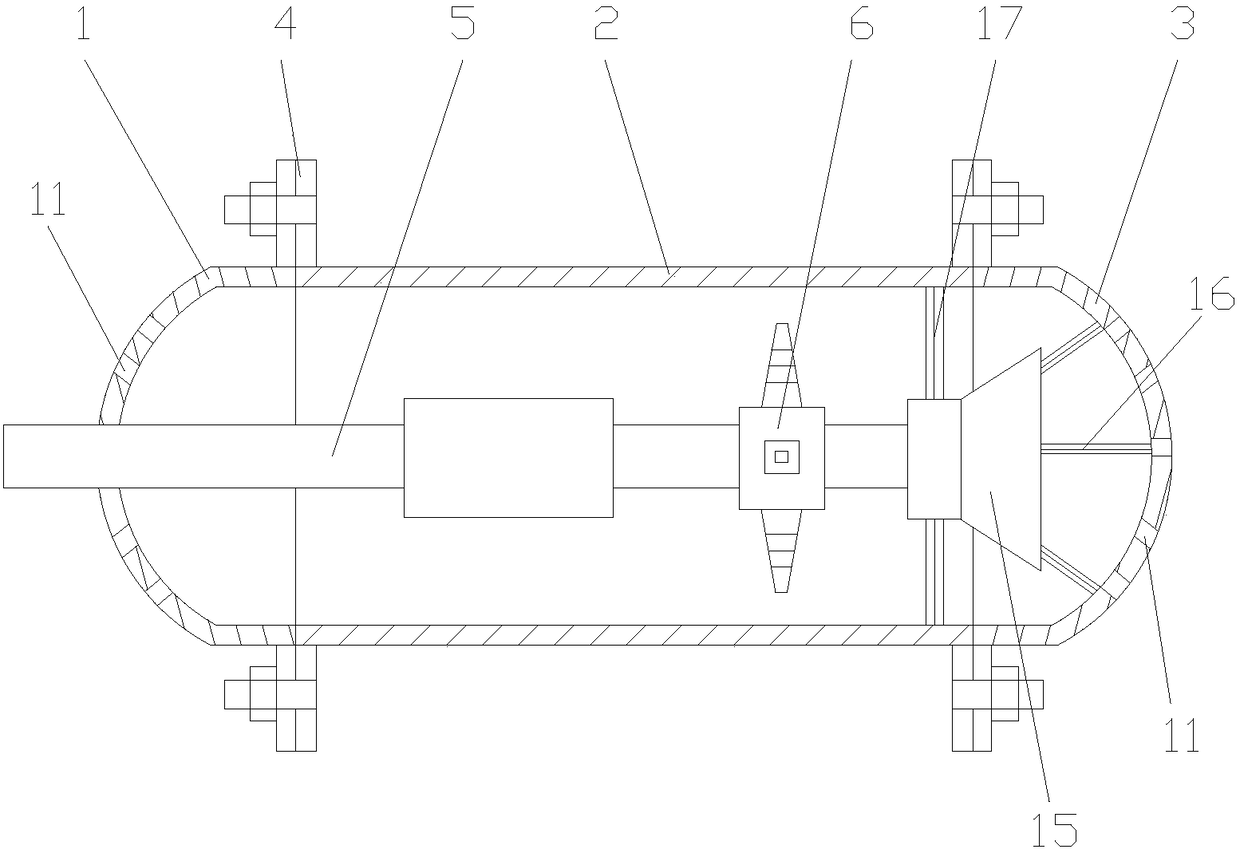
[0018] Such as figure 1 , figure 2 , image 3 with Figure 4 As shown, the heat-dissipating motor for a home appliance mixer includes a front cover 1, a body 2 and a rear cover 3, and the front cover 1, the body 2 and the rear cover 3 are all connected by a flange 4, and the outer wall of the body 2 is provided with a There are some heat dissipation fins 7 and heat dissipation grooves 8, the heat dissipation grooves 8 are located between adjacent heat dissipation fins 7, and each heat dissipation fin 7 is provided with some through holes 9, and the through holes 9 on the adjacent heat dissipation fins 7 Symmetrically distributed, the outer edge of each cooling fin 7 is provided with a number of grooves 10 at intervals, the motor shaft 5 is provided inside the fuselage 2, the r...


PUM


Abstract

The invention discloses a heat dissipation type motor for a domestic stirrer. The heat dissipation type motor comprises a front cover, a machine body and a back cover; the front cover, the machine body and the back cover are connected through flanges; multiple heat dissipation fins and heat dissipation grooves are formed in the outer wall of the machine body, and the heat dissipation grooves are formed between adjacent heat dissipation fins; multiple through holes are formed in each heat dissipation fin, and the through holes in the adjacent heat dissipation fins are symmetrically distributed;multiple grooves are formed in the outer edge of each heat dissipation fin at intervals; a motor shaft is arranged in the machine body; the back part of the motor shaft is sleeved with a fan; multiple heat dissipation holes are formed in the end planes of the front cover and the back cover; and multiple axially-distributed reinforcing ribs are uniformly arranged on the inner side wall of the backcover. The heat dissipation type motor has the characteristics of improvement of heat dissipation performance and prolonging of service life.

Description

technical field [0001] The invention relates to a motor for a home appliance mixer, in particular to a heat dissipation motor for a home appliance mixer. Background technique [0002] A general motor is mainly composed of two parts: the fixed part is called the stator, and the rotating part is called the rotor. In addition, there are end covers, fuselages, junction boxes, etc. The role of the stator is to generate a magnetic field and to provide mechanical support for the motor. The stator of the motor includes a stator core and a stator winding. The stator winding is embedded in the stator core, and an induced electromotive force is generated when a current passes through to realize electric energy conversion. When the motor is running, the heat generated by the internal loss is transmitted to the fuselage through the iron core, and then dissipated from the surface of the fuselage to the surrounding air. For high-speed motors for home appliance mixers, the motor rotor an...

Claims


Application Information

Patent Timeline
Patent Type & Authority Applications(China)
IPC IPC(8): H02K5/18H02K5/20H02K9/06H02K9/26
CPCH02K5/18H02K5/20H02K9/06H02K9/26
Inventor 林峰
Owner 湖州正鸣塑胶科技有限公司
Learn More