Vehicle controller based on model design
A vehicle controller and model design technology, applied in computer control, simulator, program control, etc., can solve the problems of vehicle controller hardware function, driving software and control method description, time-consuming and labor-intensive testing work, etc. Achieve the effect of enriching hardware resources and interfaces, improving development efficiency, and being easy to cut
- Summary
- Abstract
- Description
- Claims
- Application Information
AI Technical Summary
Problems solved by technology
Method used
Image
Examples
Embodiment 1
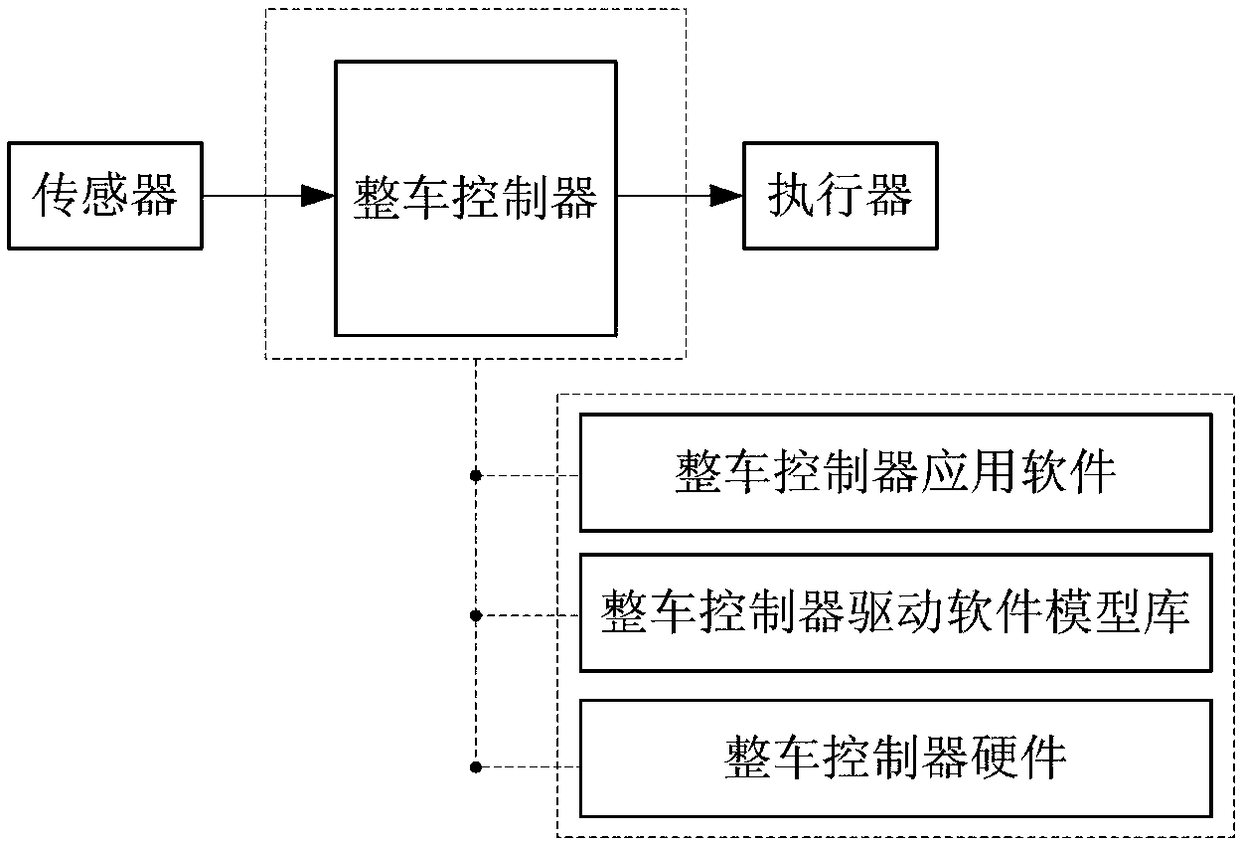
[0025] see figure 1 A model-based design vehicle controller includes vehicle controller hardware, vehicle controller driver software model library and vehicle controller application software.
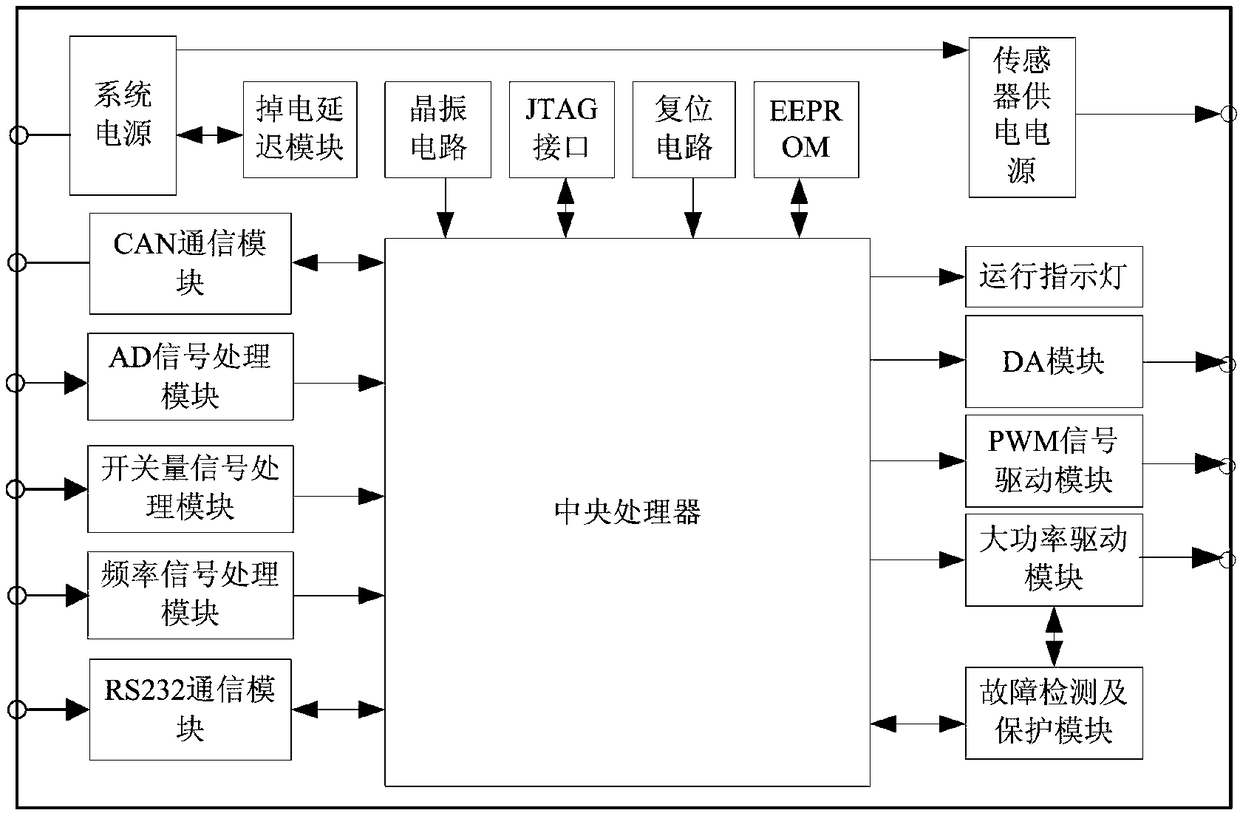
[0026] see figure 2 , the hardware module of the vehicle controller includes a system power supply and management module, a central processing unit, a storage module, an input signal processing module, an output signal processing module, a communication module, a fault detection and protection module and connectors;
[0027] see figure 2 , the central processing unit adopted is a 32-bit processor with a main frequency of 150MHz and supports floating-point operations;
[0028] see figure 2 , the system power supply and management module includes a system power supply module, a sensor power supply module and a power-off delay module, and the system power supply module converts the power supply of the vehicle controller into 7.5V, 5V, 3.3V, 1.8V is the power supply for the central p...
Embodiment 2
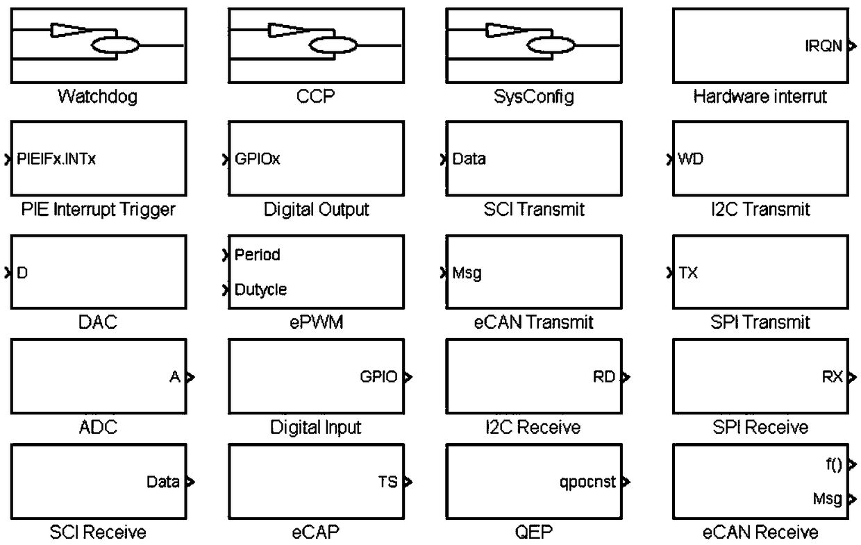
[0034] see image 3 , is the vehicle controller driver software model library. The software modules in the model library replace the basic software realized by traditional handwritten C codes, and are integrated in the Matlab / Simulink software library, and the input and output interfaces of the control strategy (application software) are respectively connected to the corresponding software library according to the signal type. The input and output modules in the system are connected to make the application software and the basic software seamlessly connected. All of them are built in the Matlab / Simulink environment. After the simulation and verification are completed, the product-level C code is automatically generated through configuration and flashed through the Bootloader. Write to the CPU, test and calibrate, and finally realize the rapid prototype development, testing and mass production of the vehicle controller. The vehicle controller driver software model library incl...
Embodiment 3
[0050] see Figure 4 , is the application software development environment built by using the driver model library, mainly including a system configuration module 401 , a monitoring and calibration variable 402 , a periodic task scheduling module 403 and a periodic subtask module 404 .
[0051] see Figure 4 , the monitoring and calibration variable 402 is used to create a variable interface that needs to be monitored and calibrated;
[0052] see Figure 4 ,use image 3 The peripheral interrupt triggering module and the interrupt response module in the set up the periodic task scheduling module 403 to realize the setting of the calling cycle;
[0053] see Figure 4 , the periodic subtask module 404 is used to execute the periodic tasks of the application software.
PUM
 Abstract
Description
Claims
Application Information
 - R&D Engineer
- R&D Manager
- IP Professional
- Industry Leading Data Capabilities
- Powerful AI technology
- Patent DNA Extraction
Browse by: Latest US Patents, China's latest patents, Technical Efficacy Thesaurus, Application Domain, Technology Topic, Popular Technical Reports.
© 2024 PatSnap. All rights reserved.Legal|Privacy policy|Modern Slavery Act Transparency Statement|Sitemap|About US| Contact US: help@patsnap.com


