


Quick Research
Generate reliable direction feasibility study reports for your R&D in just a few steps.

Technical Q&A
Discover and master advanced knowledge NOW. Basics, ideas, possibilities, all at once.

Find Solutions
As an expert in R&D theories, this can generate solutions to your technical problems instantly.

Evaluate Feasibility
Analyze your overall solution with one click, know your potential R&D risks in advance.

Monitor Landscape
Get weekly tech updates, stay abreast of the latest tech innovations and key insights.
Detection device, detection method and electronic imaging device
A detection device and electronic imaging technology, which is applied in the field of detection devices and electronic imaging devices, can solve the problem of high cost
- Summary
- Abstract
- Description
- Claims
- Application Information
AI Technical Summary
Problems solved by technology
Method used
Image

Examples
Embodiment 1
[0034] This embodiment provides an electronic imaging device, including a main body and a process box detachably installed in the main body, a power receiving part is arranged on the process box, and a detection device is also arranged in the main body, and the detection device detects the power receiving part To detect the process cartridge, that is, to detect whether the process cartridge is installed in place in the main body, or whether the model of the process cartridge installed in the main body matches the model of the electronic imaging device.
[0035] In the following, the detection device detects whether the developing unit 2 is installed in place in the main body 10 of the electronic imaging device as an example for description.
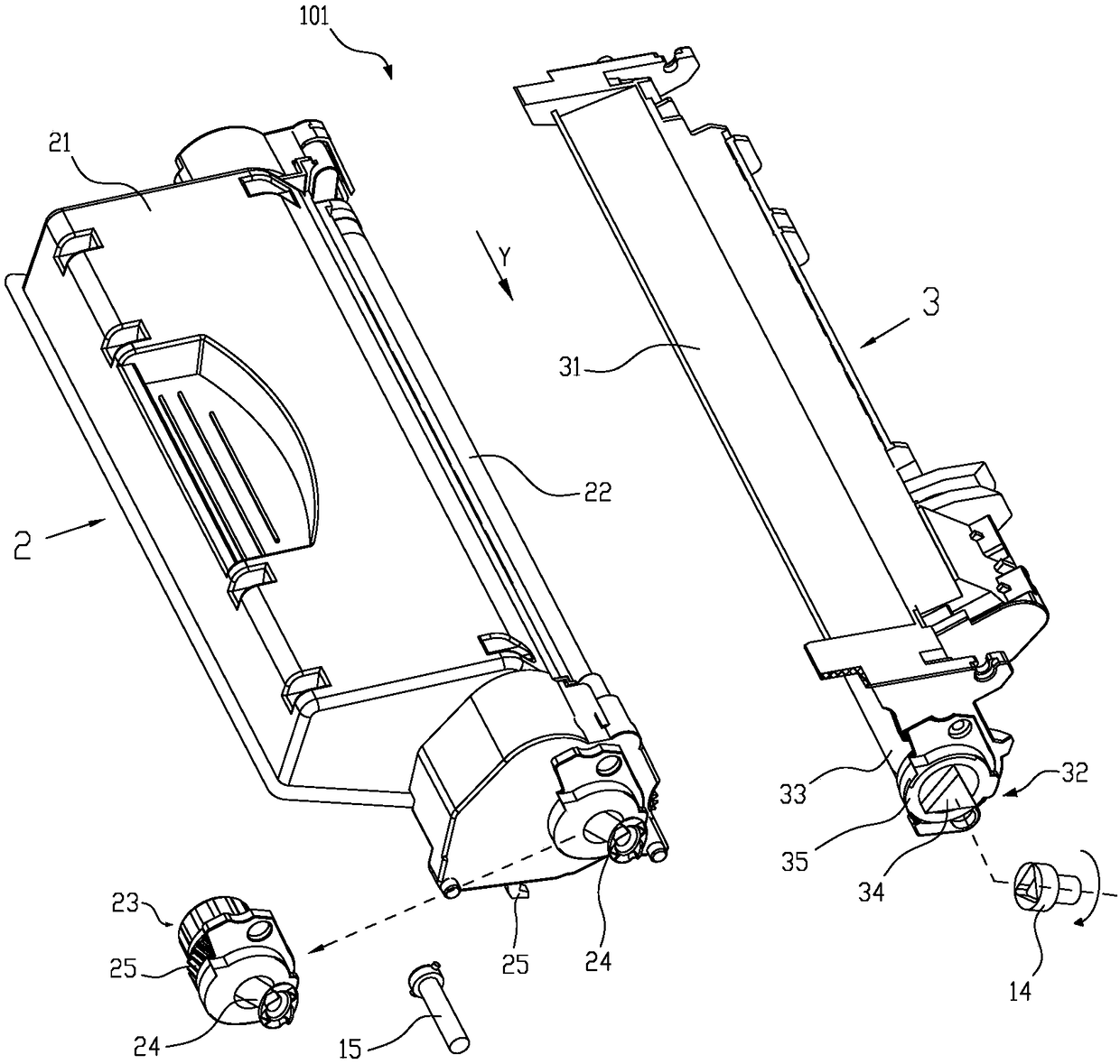
[0036] Such as Figure 5 As shown, the third power receiving unit 70 is arranged at one end of the developing unit 2 along the Y direction, and includes a third power receiving member 74 and a third hub 75. When the developing unit 2 is i...
Embodiment 2
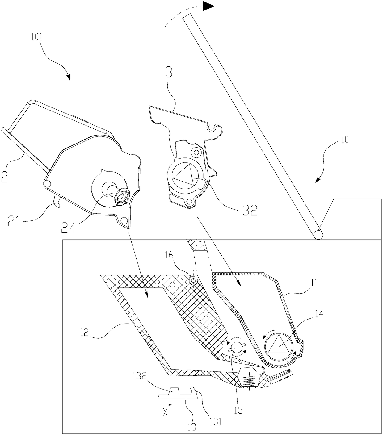
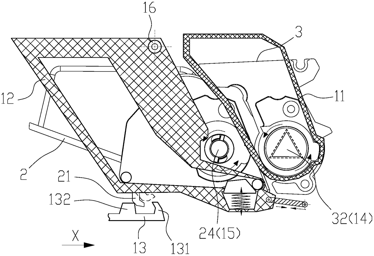
[0047] Such as Figure 7 , Figure 8 As shown, in this embodiment, the detection device 40 is disposed on the opposite side of the first driving member 15 along the direction P, that is, the detection device 40 is disposed on the path during the installation process of the process cartridge 101 to the electronic imaging device. During the process of installing the developing unit 2 into the main body 10, one end of the first power receiving member 24 along the Y direction abuts against the opposite end of the contact rod 41 along the Y direction and pushes the contact rod 41 to move along the Y direction to the set position. position, so that the first conductive member 43 of the detection device 40 abuts against the second conductive member 44, and the CPU automatically determines that the process cartridge is installed in place, or the CPU detects the model and electronic imaging device of the developing unit 2 installed in the main body 10. match the model of the device. ...
Embodiment 3
[0052] This embodiment provides an electronic imaging device, including a main body and a process box detachably installed in the main body, a power receiving part is arranged on the process box, and a detection device is also arranged in the main body, and the detection device detects the power receiving part To detect the process cartridge, that is, to detect whether the process cartridge is installed in place in the main body, or whether the model of the process cartridge installed in the main body matches the model of the electronic imaging device.
[0053] In this example, if Figure 9 As shown, the first driving component 15 and the detection device 40 are basically the same as those in the first embodiment, and will not be repeated here.
[0054] In this embodiment, the third power receiving unit 70 in the first embodiment is replaced by the fourth power receiving unit 51 . The fourth power receiving unit 51 includes a fourth power receiving part 52 capable of engaging...
PUM
 Abstract
Description
Claims
Application Information
 - R&D Engineer
- R&D Manager
- IP Professional
- Industry Leading Data Capabilities
- Powerful AI technology
- Patent DNA Extraction
Browse by: Latest US Patents, China's latest patents, Technical Efficacy Thesaurus, Application Domain, Technology Topic, Popular Technical Reports.
© 2024 PatSnap. All rights reserved.Legal|Privacy policy|Modern Slavery Act Transparency Statement|Sitemap|About US| Contact US: help@patsnap.com