
Device and method for removing clogging of tailings drainage and seepage facilities

A technology of removing device and blockage, which is applied in the direction of sewage removal, water supply device, grease/oily substance/float removal device, etc., which can solve the problems of difficulty in cleaning, removing the blockage layer, and increasing the condensation of fine particle belt drainage system. , to achieve the effect of strong operability

Active Publication Date: 2019-12-31
UNIV OF SCI & TECH BEIJING
View PDF6 Cites 0 Cited by
  • Summary
  • Abstract
  • Description
  • Claims
  • Application Information

AI Technical Summary

Problems solved by technology

However, a certain amount of flocculant is often used in the thickening process, and the use of flocculant will increase the coagulation of (ultra)fine particles in the drainage system, which will increase the possibility of chemical clogging in the tailings that originally contain beneficiation agents, and further reduce the drainage performance.
3. Tailings often contain a certain amount of microorganisms (bacteria) and active minerals. The interaction between microorganisms and chemical components will accelerate the oxidation of active minerals and the precipitation of reaction products, forming biological (chemical) silting, and the formation of biological silting form, which is more difficult to clean
How to effectively and non-destructively remove the clogging layer of the tailings pond drainage facilities that have been silted up is still in a blank stage in the research and development of devices and methods

Method used


Image

  • Device and method for removing clogging of tailings drainage and seepage facilities
  • Device and method for removing clogging of tailings drainage and seepage facilities
  • Device and method for removing clogging of tailings drainage and seepage facilities

Examples


Embodiment Construction

[0021] In order to make the technical problems, technical solutions and advantages to be solved by the present invention clearer, the following will describe in detail with reference to the drawings and specific embodiments.

[0022] The invention provides a device and method for removing clogging of tailings seepage drainage facilities.

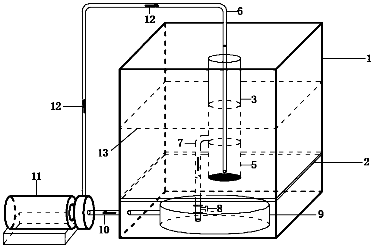
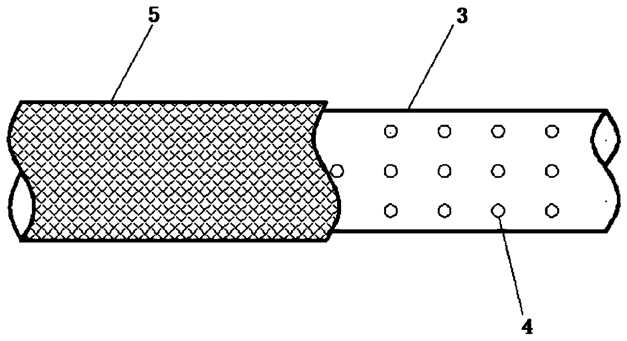
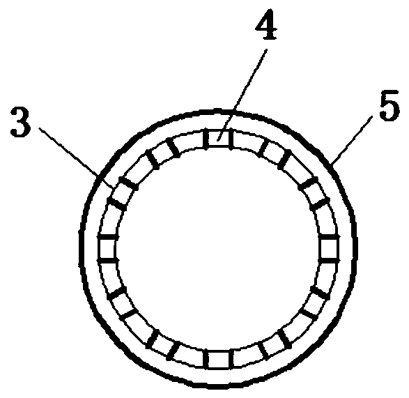
[0023] Such as figure 1 As shown, the device includes a box body 1, a waterproof bottom plate 2, a drainage pipe 3, a geotextile reverse filter layer 5, a hydraulic dredging pipe 6, a dredging drainage pipe 7, a small water flow meter 8, and a dredging solution container 9 , suction pipe 10 and centrifugal pump 11, waterproof floor 2 is installed at the bottom of casing 1, the suction port of centrifugal pump 11 is connected with suction pipe 10, and the outlet of centrifugal pump 11 is connected with hydraulic dredging pipe 6; figure 2 with image 3 As shown, the seepage pipe 3 ends are provided with seepage holes 4, and the seepage hole...


PUM


Abstract

The invention provides a tailings drainage installation clogging clearing device and method and belongs to the technical field of tailings drainage installation clogging clearing. The device comprisesa box, a water isolating bottom plate, a drainage pipe, a geotechnical cloth inverted filter layer, a hydraulic dredging pipe, a dredging drainage pipe, a small water flow meter, a dredging solutioncontainer, a water drawing pipe and a centrifugal pump. The water isolating bottom plate is mounted at the bottom of the box, and a suction inlet of the centrifugal pump is connected with the water drawing pipe while an outlet of the same is connected with the hydraulic dredging pipe; water permeable holes are distributed in the end of the drainage pipe, the hydraulic dredging pipe is arranged inside the drainage pipe, and a water incoming end of the hydraulic dredging pipe is connected with the centrifugal pump; the small water flow meter is arranged at the water outgoing end of the dredgingdrainage pipe, and the dredging solution container is arranged at the bottom end of the water isolating bottom plate. The device is simple in structure, simple and convenient to use and capable of effectively and efficiently dredge clogging of a tailings pond drainage installation in an undamaged manner according to actual working conditions.

Description

technical field [0001] The invention relates to the technical field of clogging removal of tailings drainage facilities, in particular to a device and method for removing clogging of tailings drainage facilities. Background technique [0002] Tailings pond is a place where metal and non-metal mines are used to store tailings or other industrial waste after crushing and sorting of ores. Tailings pond is an important part of mine safety production, and it is also one of the major sources of danger in this industry. In the past ten years, due to the increasing production scale of my country's mining enterprises, the discharge of tailings has also increased significantly. Many mines in China have adopted the method of raising tailings dams and expanding storage capacity to extend the service life of tailings ponds, and the accompanying safety problems of tailings ponds have gradually emerged. One of the major safety hazards is the function of seepage drainage facilities Failur...

Claims


Application Information

Patent Timeline
Patent Type & Authority Patents(China)
IPC IPC(8): E03F1/00E03F5/22E03F5/14E02D3/10
CPCE02D3/10E03F1/00E03F5/14E03F5/22
Inventor 尹升华邵亚建李斌张连富陈勋张海胜
Owner UNIV OF SCI & TECH BEIJING
Learn More