Energy-saving condensing piece of compact spinning device

A compact spinning and agglomeration tank technology, applied in spinning machines, textiles and papermaking, drafting equipment, etc., can solve the problems of large opening area, high energy consumption, large air flow, etc., to reduce air flow and ensure agglomeration effect. , the effect of reducing the cross-sectional area

Inactive Publication Date: 2018-07-27
JINJIANG HAOMING MACHINERY
View PDF0 Cites 1 Cited by
  • Summary
  • Abstract
  • Description
  • Claims
  • Application Information

AI Technical Summary

Problems solved by technology

However, in the existing compact spinning device, the traditional accumulating piece is slotted as a whole, the length of the slot is long, and the opening area is large, so the air flow used is large, and the negative pressure fan is required to provide sufficient negative pressure and air flow to ensure compact spinning. normal operation of the device
Therefore, the existing compact spinning device has high energy consumption, does not meet the requirements of energy saving and emission reduction in today's society, and the production cost is also high

Method used


Image

  • Energy-saving condensing piece of compact spinning device
  • Energy-saving condensing piece of compact spinning device
  • Energy-saving condensing piece of compact spinning device

Examples


Embodiment 1

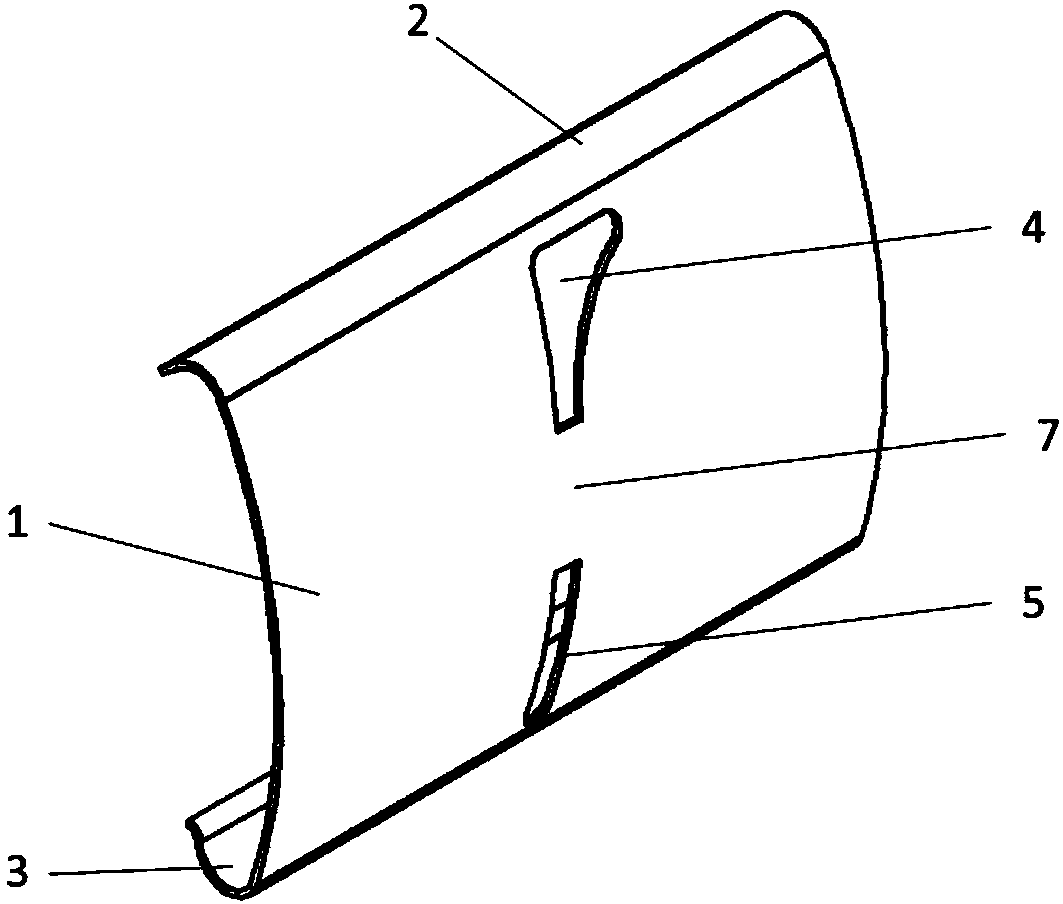
[0019] Such as image 3 As shown, an energy-saving accumulating sheet for a compact spinning device includes an accumulating sheet main body 1, an upper curved arc 2, and a lower curved arc 3. An upper accumulating groove 4 is opened on the upper part of the accumulating sheet main body 1, and a lower accumulating groove 5 is opened on the lower part of the accumulating sheet main body. , the transition zone 7 is in the middle of the upper collecting groove and the lower collecting groove. Wherein, both the upper collecting groove and the lower collecting groove are single grooves, and the notch center lines of the upper collecting groove and the lower collecting groove coincide, and the main body of the collecting sheet is made of stainless steel.

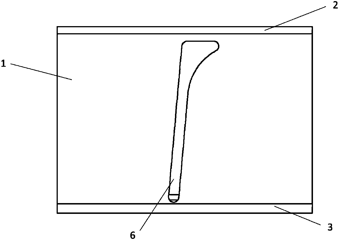
[0020] figure 1 Shown is a prior art single groove packing piece. Will image 3 The energy-saving compacting sheet of the compact spinning device shown is according to Figure 5 The way shown is assembled on the special-shaped...

Embodiment 2

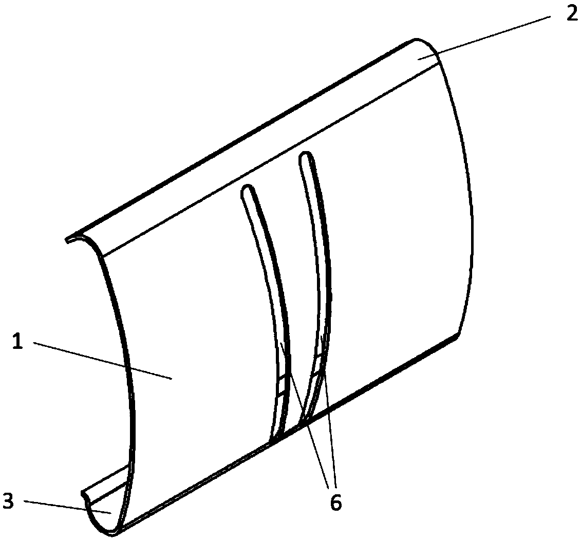
[0022] Such as Figure 4 As shown, an energy-saving accumulating sheet for a compact spinning device includes an accumulating sheet main body 1, an upper curved arc 2, and a lower curved arc 3. An upper accumulating groove 4 is opened on the upper part of the accumulating sheet main body 1, and a lower accumulating groove 5 is opened on the lower part of the accumulating sheet main body. , the transition zone 7 is in the middle of the upper collecting groove and the lower collecting groove. Wherein, both the upper collecting groove and the lower collecting groove are double grooves, and the centerlines of the notches corresponding to the upper collecting groove and the lower collecting groove coincide, and the main body of the collecting sheet is made of elastic metal.


PUM


Abstract

The invention discloses an energy-saving condensing piece of a compact spinning device. The energy-saving condensing piece comprises a condensing piece body, an upper condensing groove, a transition area, a lower condensing groove, an upper arc and a lower arc. The condensing piece is fixedly installed on a special pipe through the upper arc and the lower arc; because the upper and lower condensing grooves are arranged and the transition area is arranged in the middle, the total opening area of the condensing grooves is reduced, the air flow rate is reduced, the workload of a negative pressureblower is reduced, accordingly, energy consumption is reduced, the effects of energy conservation and emission reduction are achieved, and meanwhile, the condensing effect is ensured.

Description

technical field [0001] The invention relates to a compact spinning device, in particular to an energy-saving gathering sheet for a compact spinning device. Background technique [0002] In the compact spinning technology, collecting grooves are set on the collecting sheet for special-shaped tubes, and the airflow passes through the collecting grooves to collect the spinning yarn. After the spinning yarn is gathered by the airflow, the structure becomes compact and the twisting triangle area is reduced, thereby improving the quality of the yarn. index. However, in the existing compact spinning device, the traditional accumulating piece is slotted as a whole, the length of the slot is long, and the opening area is large, so the air flow used is large, and the negative pressure fan is required to provide sufficient negative pressure and air flow to ensure compact spinning. normal operation of the device. Therefore, the existing compact spinning device has high energy consumpt...

Claims


Application Information

Patent Timeline
IPC IPC(8): D01H5/72
CPCD01H5/72
Inventor 彭子刚
Owner JINJIANG HAOMING MACHINERY
Why Eureka
Try Eureka