A piezoelectric stick-slip motor adopting an I-shaped structure and its driving method
An I-shaped, piezoelectric technology, applied in the direction of piezoelectric effect/electrostrictive or magnetostrictive motors, generators/motors, electrical components, etc., can solve the problem of unadjustable preload, small output thrust, and poor stability and other problems, to achieve the effect of easy realization, convenient pre-tightening force and simple structure
- Summary
- Abstract
- Description
- Claims
- Application Information
AI Technical Summary
Problems solved by technology
Method used
Image
Examples
specific Embodiment approach 1
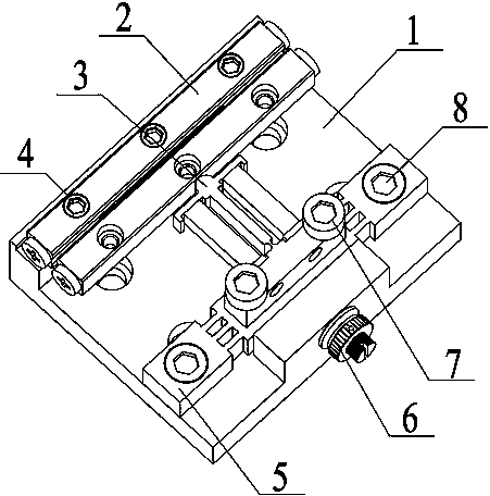
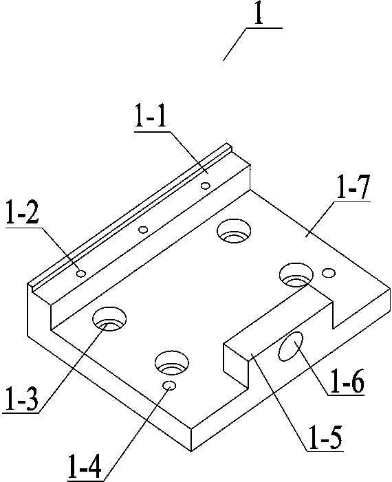
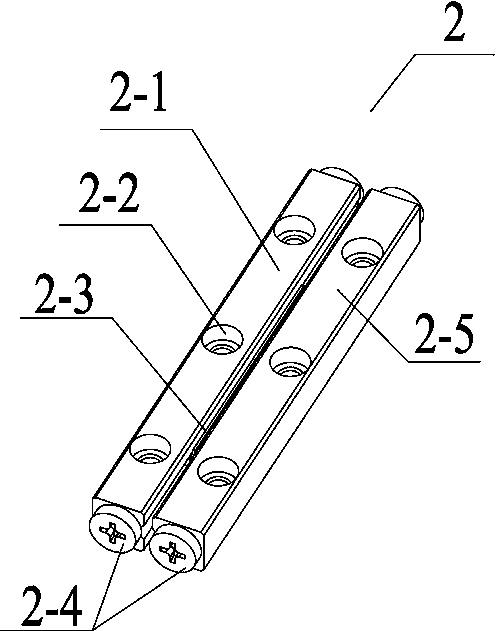
[0022] Specific implementation mode one: combine Figure 1~Figure 7 This embodiment will be described. This embodiment provides a specific embodiment of a piezoelectric stick-slip motor with an I-shaped structure and a driving method thereof. The piezoelectric stick-slip motor with an I-shaped structure and its driving method are composed of a base 1, a double row cross roller guide rail 2, a driving stator 3, a guide rail mounting bolt 4, a loading mechanism 5, a thread pair 6, and a driving stator The mounting bolts 7 and the loading mechanism mounting bolts 8 are composed; the double-row cross roller guide rail 2 is installed on the base 1 through the guide rail mounting bolts 4, and the loading mechanism 5 is installed on the base 1 through the loading mechanism mounting bolts 8 to drive the stator 3 is installed on the loading mechanism 5 by driving the stator mounting bolt 7, and the thread pair 6 is glued and installed on the thread pair installation holes 1-6.
[002...
specific Embodiment approach 2
[0028] Specific implementation mode two: combination Figure 8 This embodiment is described. This embodiment provides a specific implementation of a piezoelectric stick-slip motor with an I-shaped structure and its driving method. The piezoelectric stick-slip motor with an I-shaped structure and its driving method are as follows shown.
[0029] The composite excitation electric signal adopted in the excitation method is realized. The composite excitation electric signal includes a friction regulation wave and a driving wave. By superimposing the friction regulation wave on the fast power-on stage of the driving wave, the I-shaped flexible hinge mechanism is excited in the rapid deformation stage. In the state of micro-pair high-frequency resonance, based on the ultrasonic anti-friction effect, the frictional resistance between the I-shaped flexible hinge mechanism and the movable guide rail in the rapid deformation stage is reduced; the driving wave is a sawtooth wave, and the...
PUM
 Abstract
Description
Claims
Application Information
 - R&D
- Intellectual Property
- Life Sciences
- Materials
- Tech Scout
- Unparalleled Data Quality
- Higher Quality Content
- 60% Fewer Hallucinations
Browse by: Latest US Patents, China's latest patents, Technical Efficacy Thesaurus, Application Domain, Technology Topic, Popular Technical Reports.
© 2025 PatSnap. All rights reserved.Legal|Privacy policy|Modern Slavery Act Transparency Statement|Sitemap|About US| Contact US: help@patsnap.com


