
Surface frame tenon

A frame tenon and surface frame technology, applied to the surface frame tenon. It can solve the problems of high labor cost and achieve the effect of simple assembly, easy disassembly and transportation, and stable structure

Pending Publication Date: 2018-07-24
苏州铨木智能科技有限公司
View PDF0 Cites 4 Cited by
  • Summary
  • Abstract
  • Description
  • Claims
  • Application Information

AI Technical Summary

Problems solved by technology

[0004] The traditional mortise and tenon structure is mostly hand-polished, which requires the skilled skills of the craftsman, accurate calculation and measurement, so that the furniture can fit perfectly after assembly and last for a long time. Due to the limitation of manual polishing, the mortise and tenon structure designed by the craftsman Among them, the mortise is mostly a right-angled square tenon, and the mortise is a rectangular or rectangular through hole. In today's society, labor costs are getting higher and higher, and there are fewer and fewer skilled craftsmen. Moreover, people have high requirements for the appearance and aesthetics of products. It is getting higher and higher. In order to improve production efficiency, reduce production costs, and at the same time, improve product aesthetics and meet people's needs, we need a mortise and tenon structure that is suitable for machining and has a stable assembly structure.

Method used


Image

  • Surface frame tenon
  • Surface frame tenon
  • Surface frame tenon

Examples


Embodiment 1

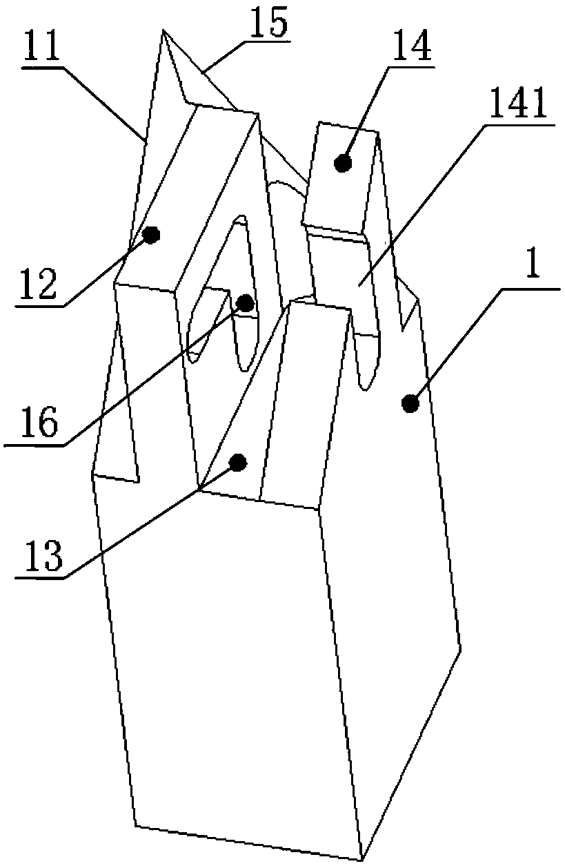
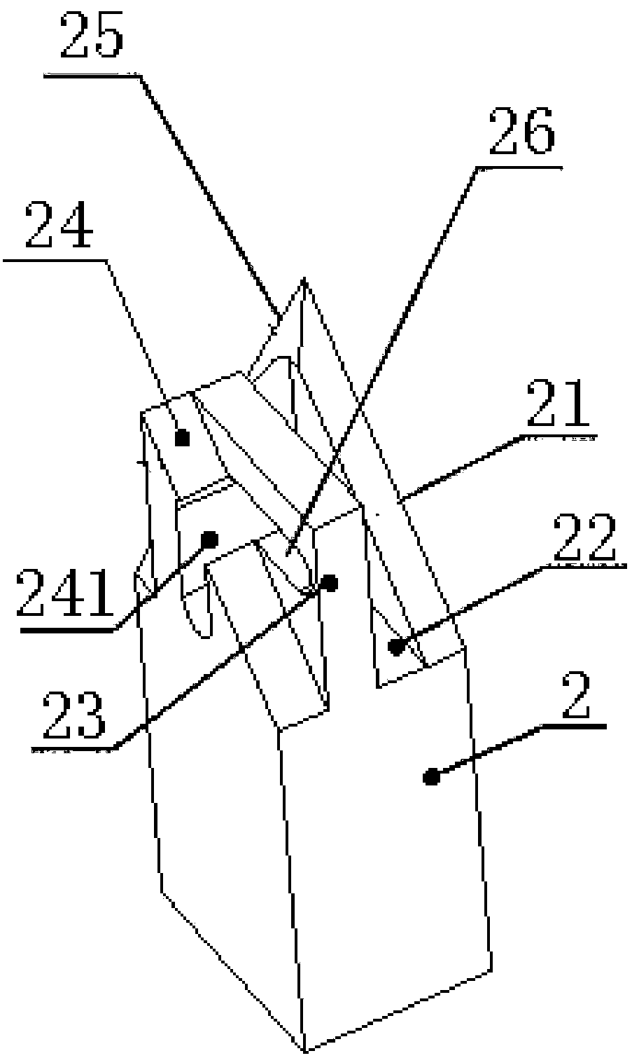
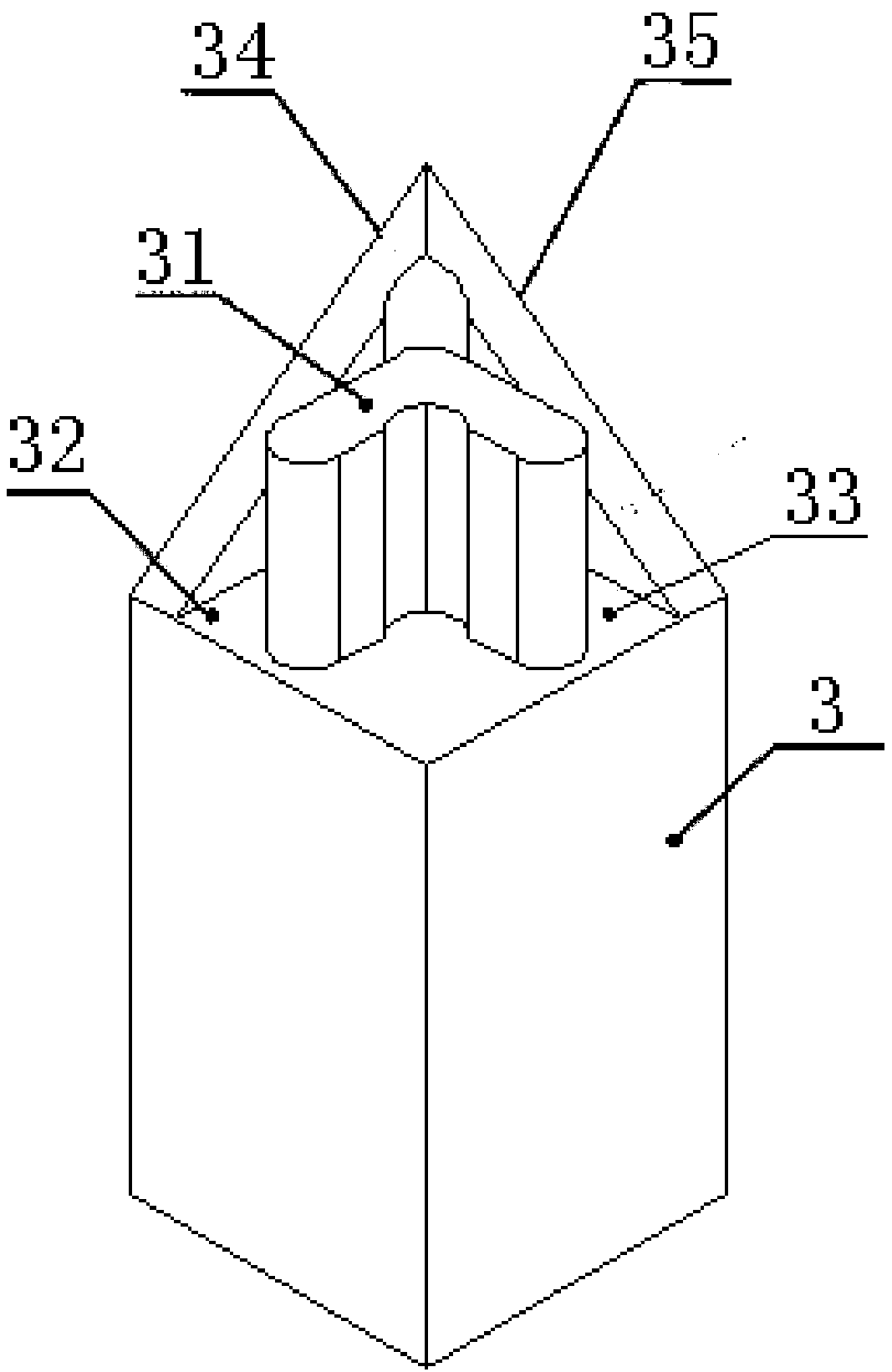
[0033] Embodiment one: see Figure 1-5 As shown, a surface frame tenon includes a first surface frame tenon 1, a second surface frame tenon 2 and a third surface frame tenon 3, and the two of the three are perpendicular to each other and assembled through the tenon head and the tenon groove. One side frame tenon 1, the second side frame tenon 2, and the third side frame tenon 3 respectively include the outer edge surface part and the inner tenon head part, the first side frame tenon 1, the second side frame tenon 2, and the third side frame tenon 3 There are two hypotenuses on the outer edge surface of the top respectively, and the six hypotenuses are overlapped in pairs, and the combined corners after the assembly of the first frame tenon 1, the second frame tenon 2, and the third frame tenon 3 are divided into six 45 ° angle; in the inner tenon part, the first socket 16 is provided on the first tenon 12 of the first surface frame tenon 1, and the second tenon 23 is provided ...


PUM


Abstract

The invention discloses a surface frame tenon. The surface frame tenon comprises a first surface frame tenon, a second surface frame tenon and a third surface frame tenon; and the three are pairwise perpendicular, and are assembled through tenon heads and tenon grooves. The surface frame tenon is characterized in that the first surface frame tenon, the second surface frame tenon and the third surface frame tenon respectively comprise outer edge surface parts and inner tenon head parts; the outer edge surfaces of the first, second and third surface frame tenons are respectively provided with two inclined edges; six inclined edges are pairwise overlapped for dividing a combined turning angle after assembly of the first surface frame tenon, the second surface frame tenon and the third surfaceframe tenon into six angles of 45 degrees; a first insertion hole is formed in the first tenon head of the first surface frame tenon; a second insertion hole is formed in the second tenon head of thesecond surface frame tenon; the first insertion hole and the second insertion hole are overlapped to form a third tenon hole of the third surface frame tenon; and the tenon head of the third surfaceframe tenon is inserted in the third tenon hole from a Y-axle direction to lock the first surface frame tenon and the second surface frame tenon in left and right X-axle directions. Furniture assembled through the structure is flat and beautiful in appearance and unique in artistic effect; and the surface frame tenon is simple and stable in structure, reasonable in design and convenient to machineand assemble.

Description

technical field [0001] The invention relates to the field of mortise and tenon joint structures, in particular to a surface frame tenon. Background technique [0002] Mortise and tenon is the main structural method of ancient Chinese furniture. It is a connection method that combines concave and convex parts on two components. Mortise and tenon joints are also called the soul of wooden furniture. The protruding mortise and the recessed mortise on the wooden components simply bite together to combine the wooden components. Due to the different shapes of the connecting components, an ever-changing pattern is derived from this. Combination methods make wooden furniture achieve the perfect unity of function and structure. [0003] The mortise and tenon structure can be classified according to the structure and can be roughly divided into three types: 1. The joint of the surface and the surface can also be the combination of two sides, or the joint structure of the surface and t...

Claims


Application Information

Patent Timeline
IPC IPC(8): F16B12/20
CPCF16B12/20
Inventor 代彭飞
Owner 苏州铨木智能科技有限公司
Learn More