Disk body separation mechanism and feeding device

一种分离机构、盘体的技术,应用在输送机控制装置、输送机、机械手等方向,能够解决结构复杂、控制复杂、大空间等问题,达到控制简单、不易操作失误、节省空间的效果

Pending Publication Date: 2018-07-24
WORLD PRECISION MANUFACTURING (DONGGUAN) CO LTD
View PDF6 Cites 18 Cited by
  • Summary
  • Abstract
  • Description
  • Claims
  • Application Information

AI Technical Summary

Problems solved by technology

[0002] In order to improve efficiency and save space, disk-shaped (sheet-shaped) objects are often stacked together for storage and transportation. When in use, they need to be separated separately. Currently, the structure of manipulator + suction cup is often used to absorb and transport disk-shaped objects, which is large in size. , The structure is complex. In use, it not only takes up too much space, but also needs to control the movement of the suction cup and the movement of the manipulator separately, which is complicated to control.

Method used


Image

  • Disk body separation mechanism and feeding device
  • Disk body separation mechanism and feeding device
  • Disk body separation mechanism and feeding device

Examples


Embodiment Construction

[0027] In order to describe the technical content, structural features, achieved goals and effects of the present invention in detail, the following will be described in detail in conjunction with the embodiments and accompanying drawings.

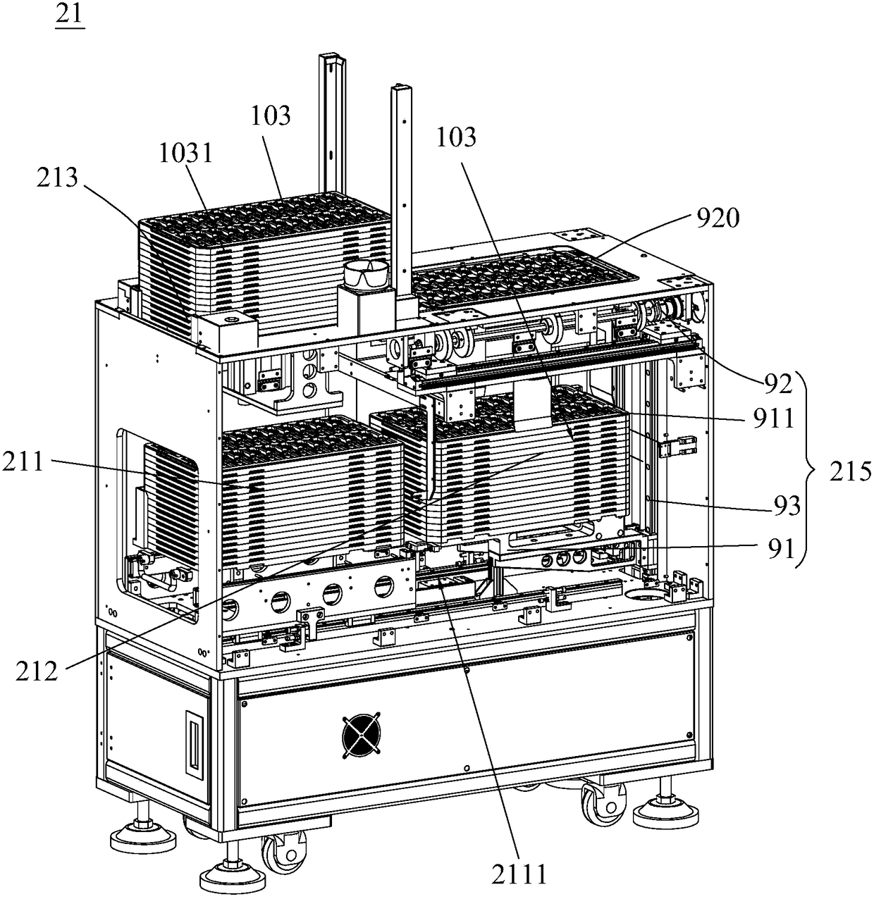
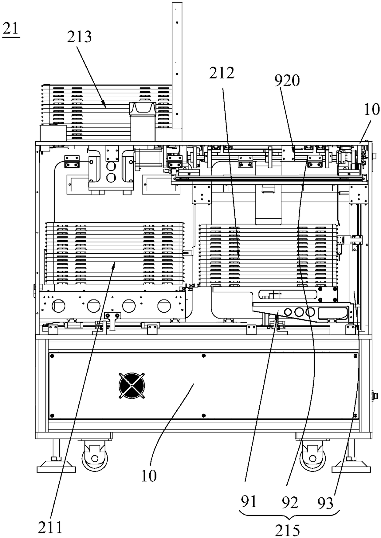
[0028] refer to figure 1 and figure 2 , the present invention discloses a feeding device 21 for feeding the production line, the feeding device 21 includes a feeding box 212 and a material shifting mechanism (2141, 2142) (such as Figure 6 As shown), a disc separation mechanism 215 is installed in the upper material box 212.

[0029] refer to figure 1 and figure 2, the disc separation mechanism 215 includes a material rack 91, a clamping assembly 92 and a lifting assembly 93, the material rack 91 has a material stacking area 911 for holding the disc 103, and a number of discs 103 are stacked on the material stacking area 911 . The clamping assembly 92 is located at the opening of the upper end of the upper material box 212 , and coo...


PUM


Abstract

The invention discloses a disk body separation mechanism. The disk body separation mechanism is used for separating stacked disk bodies. The disk body separation mechanism comprises a rack, a materialrack, a clamping assembly and a lifting assembly. The material rack is provided with a material stacking area for containing disk bodies. The clamping assembly comprises a driving motor mounted on the rack, two rotary shafts arranged oppositely, cams mounted on the two rotary shafts correspondingly and clamping blocks connected with the cams. The driving motor drives the rotary shafts to rotate.The rotary shafts drive the cams to rotate so as to drive the clamping blocks on the two opposite sides of a separation area to do telescopic motion relative to the separation area to clamp and release the disk bodies. The lifting assembly controls the clamping assembly and the material rack to move relatively. Compared with the prior art, the disk body separation mechanism has the advantages thatthe cams are matched with the lifting assembly to separate the disk bodies, and the occupied space of the disk body separation mechanism is effectively reduced; the disk body separation mechanism iseasy to control, stable in clamping and not prone to misoperation. The invention further disk a feeding device comprising the disk body separation mechanism.

Description

technical field [0001] The invention relates to material conveying, in particular to a disc separating mechanism and a feeding device for separating stacked discs. Background technique [0002] In order to improve efficiency and save space, disk-shaped (sheet-shaped) objects are often stacked together for storage and transportation. When in use, they need to be separated separately. Currently, the structure of manipulator + suction cup is often used to absorb and transport disk-shaped objects, which is large in size. , The structure is complex. In use, it not only takes up too much space, but also needs to control the movement of the suction cup and the movement of the manipulator separately, so the control is complicated. Therefore, there is an urgent need for a disk clamping assembly with small volume, simple structure and convenient control. Contents of the invention [0003] The object of the present invention is to provide a disc separation mechanism with simple stru...

Claims


Application Information

Patent Timeline
Patent Type & Authority Applications(China)
IPC IPC(8): B65G59/02B65G47/90
CPCB65G47/901B65G59/02B65G2201/0258B65G59/107B65G47/917B65G2201/022B25J15/0226B65G61/00B65G43/08
Inventor 申宇孙金锁
Owner WORLD PRECISION MANUFACTURING (DONGGUAN) CO LTD
Why Eureka
Try Eureka