
Three-position switch control system and control method

A transfer switch and control system technology, applied in electrical switches, locomotives, electrical components, etc., can solve problems such as hidden safety hazards for operators, eliminate falling or electric shock, operate easily and quickly, and reduce manpower, material resources and related resources. The effect of the configuration

Active Publication Date: 2018-07-24
CRRC TANGSHAN CO LTD
View PDF4 Cites 3 Cited by
  • Summary
  • Abstract
  • Description
  • Claims
  • Application Information

AI Technical Summary

Problems solved by technology

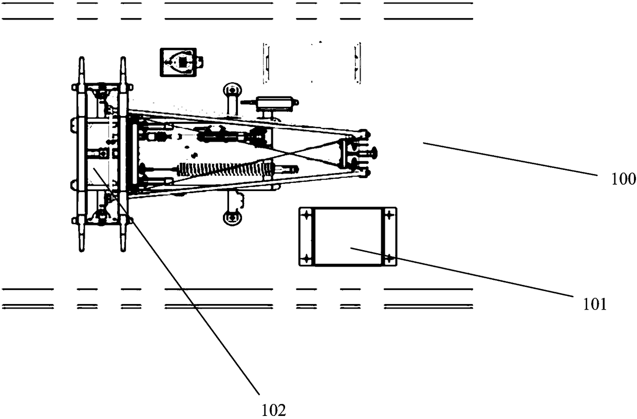
[0004] However, since the installation position of the three-position transfer switch device 101 is located on the roof 100, the operator must be a professional with corresponding qualifications, and needs to board the roof 100 with the help of professional equipment such as lifts and safety ropes; and the three-position conversion The switchgear 101 is relatively close to the pantograph 102, which will cause potential safety hazards to the personal safety of the operators when switching the state of the rail vehicle

Method used


Image

  • Three-position switch control system and control method
  • Three-position switch control system and control method
  • Three-position switch control system and control method

Examples


Embodiment 1

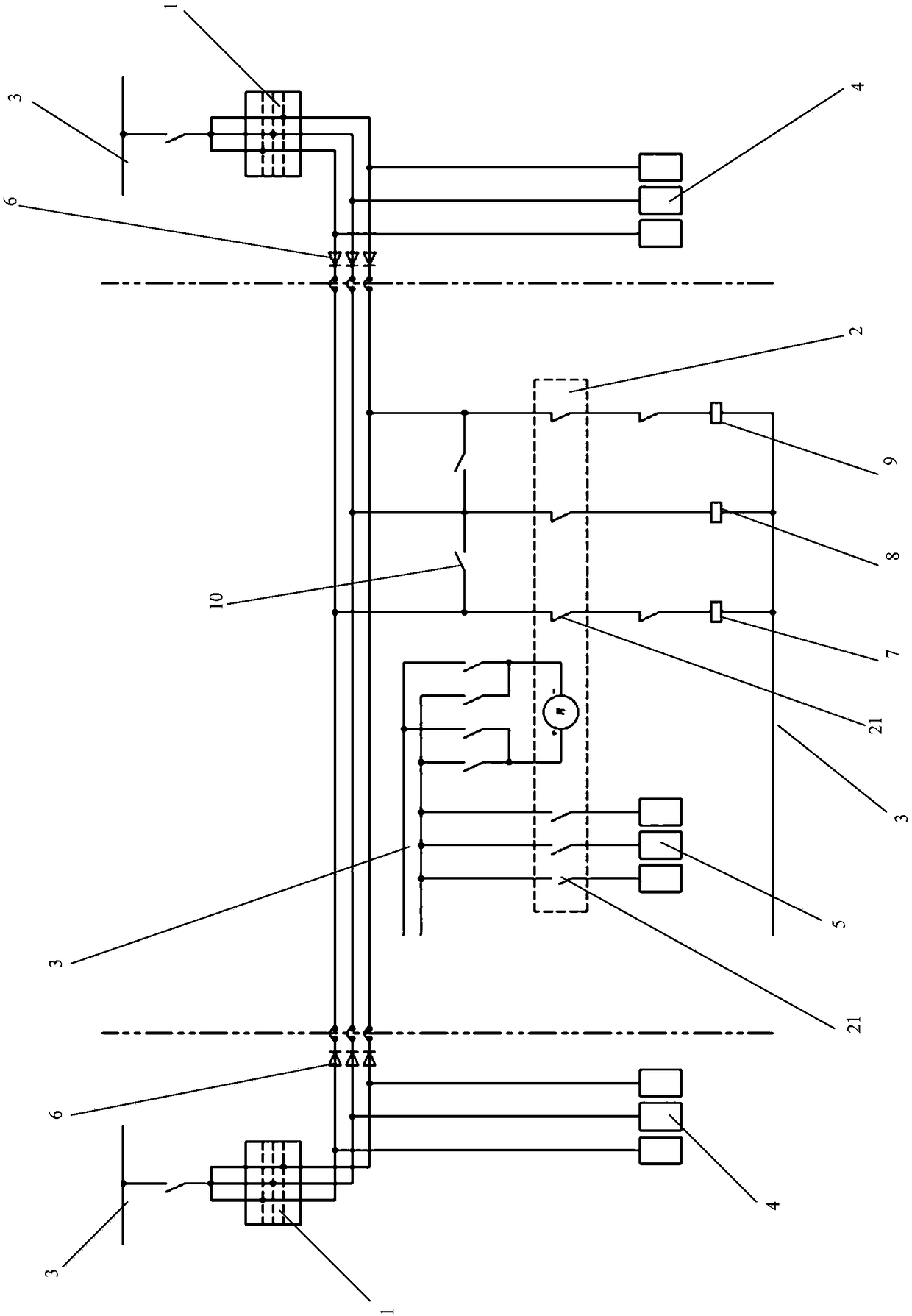
[0080] figure 2 A schematic structural diagram of a three-position transfer switch control system provided by an embodiment of the present invention; please refer to figure 2 . This embodiment provides a three-position transfer switch control system, including a control knob 1 arranged in the cab and a three-position transfer switch device 2 arranged on the roof, the three-position transfer switch device 2 and the control knob 1 Electrically connected, and the three-position transfer switch device 2 and the control knob 1 are both connected to the vehicle power supply 3;

[0081] The three-position transfer switch device 2 is provided with limit switches 21 corresponding to different control positions, and the rotation of the control knob 1 can drive the opening or closing of the limit switches 21 of different control positions, wherein the The limit switch 21 includes a running position switch, a grounding position switch and a storage position switch.

[0082] Specifica...

Embodiment 2

[0097] Figure 5 The flow chart of the three-position transfer switch control method provided by an embodiment of the present invention; please refer to Figure 5 . This embodiment provides a control method based on the above-mentioned three-position transfer switch control system, including:

[0098] Obtain the control command issued by the control knob and the current position status of the limit switch;

[0099] If the current position state matches the control command, the motor will not rotate;

[0100] If the current position state does not match the control command, the motor will rotate and drive the limit switch to switch to the corresponding control position;

[0101] Among them, the control command includes the operation bit command, the ground bit command and the library bit command.

[0102] Its specific control method can be described in detail in conjunction with the accompanying drawings. Figure 6(a)-Figure 6(c) The logic block diagram of the three-positi...


PUM


Abstract

The invention provides a three-position switch control system and control method. The control system comprises a control knob arranged in a cab and a three-position switch device arranged on the car roof, the three-position switch device is electrically connected with the control knob, and the three-position switch device and the control knob are both connected with a vehicle-mounted power supply.The three-position switch device is internally provided with limiting switches corresponding to different control positions separately, and turning-on or turning-off of the limiting switches of the different control positions is driven by the rotation of the control knob. The three-position switch control system allows a driver to realize control over the three-position switch device on the car roof in the cab, the operation is simple and fast, operation by climbing to the roof is not needed, the allocation of manpower and material resources and related resources is reduced, and potential safety hazards such as falling or electric shocking during the operation of an operator climbing to the roof are eliminated.

Description

technical field [0001] The invention relates to rail vehicle manufacturing technology, in particular to a control system and a control method for a three-position transfer switch. Background technique [0002] The three-position transfer switch device is set on the high-voltage circuit of the rail vehicle. By switching the switch to different control positions, it can realize the catenary power supply, grounding protection or connection to an external power supply of the rail vehicle. [0003] figure 1 It is a simplified diagram of the installation structure of the three-position transfer switch device in the prior art; please refer to figure 1 . In the prior art, the three-position transfer switch device 101 is generally installed on the roof 100 of the rail vehicle, and is located near the pantograph 102 on the roof 100 . The three-position changeover switch device 101 includes a box body and devices such as a three-position changeover switch arranged in the box body, a...

Claims


Application Information

Patent Timeline
Patent Type & Authority Applications(China)
IPC IPC(8): B61C17/00H01H9/26
CPCB61C17/00H01H9/26
Inventor 臧晓艳李硕王永刚苏文煜林琳岳成林潘硕张婷婷
Owner CRRC TANGSHAN CO LTD
Learn More