Tire mold vulcanizing device

A tire mold, No. 1 technology, applied to tires, household appliances, and other household appliances, etc., can solve the problems of harmful substances in exhaust gas, prone to skewing of valve core, inaccurate spring adjustment, etc., to achieve convenient use and ensure exhaust effect , good performance

Active Publication Date: 2018-07-24
合肥大道模具有限责任公司
View PDF5 Cites 1 Cited by
  • Summary
  • Abstract
  • Description
  • Claims
  • Application Information

AI Technical Summary

Problems solved by technology

[0002] The tire mold needs to be vulcanized through the tire mold after the tire blank is formed. During the vulcanization process, the air in the inner cavity of the tire mold needs to be discharged. At present, the air vent on the tire mold is usually used for exhausting, but this method is used in tires. After the air in the mold is exhausted, the liquid rubber is easy to enter the vent hole, so that the surface of the tire will appear burrs
[0003] Therefore, there is also a tire mold exhaust valve adjustment structure in the market, which is generally composed of a valve body, a valve core, a spring and other structures, but the valve core is generally prone to skewing, and the spring adjustment is relatively inaccurate, which reduces the use to a certain extent Effect and service life
The exhaust gas often contains certain harmful substances, and direct discharge also poses certain safety hazards to the health of the staff.

Method used


Image

  • Tire mold vulcanizing device

Examples


Embodiment 1

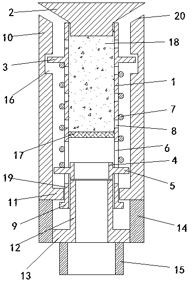
[0021] A cylindrical valve body 10 is inserted in the exhaust hole, and the valve body 10 is arranged longitudinally. The bottom of the valve body 10 is provided with a limiting neck 11, and a cylindrical valve core 1 is inserted in the valve body 10, and the valve core 1 is uniformly ringed. Two strip-shaped through holes 6 are provided, and the two strip-shaped through holes 6 are arranged vertically;

[0022] The spool 1 is inserted with a limit ring 4, and the limit ring 4 is provided with two No. 1 limit blocks 5, and the two No. 1 limit blocks 5 cooperate with two strip-shaped through holes 6;

[0023] The bottom end of the spool 1 is coaxially provided with a No. 1 connecting ring 19. The No. 1 connecting ring 19 matches the shape of the spool 1. The outer edge of the connecting ring 19 is provided with a No. 2 limit block 9, and the No. 2 limit block 9 is arranged on the limit position. Below the necking 11; the second limit block 9 is ring-shaped;

[0024] The lower ...


PUM


Abstract

The invention provides a tire mold vulcanizing device, and relates to the technical field of tire molds. A barrel-shaped valve body is inserted in an exhaust hole, the bottom of the valve body is provided with a limiting necking port, a barrel-shaped valve element is inserted in the valve body, and a plurality of strip-shaped through holes are evenly and annularly formed in the valve element. A limiting ring is inserted in the valve element and provided with a plurality of first limiting blocks, a first connection ring is coaxially arranged at the bottom end of the valve element, the outer edge of the first connection ring is provided with second limiting blocks, a push ring is coaxially inserted to the lower end of the valve element, third limiting blocks are arranged on the outer edge ofthe push ring, a second connection ring is coaxially arranged below the limiting necking port, a circular truncated cone-shaped sealing block is arranged at the top end of the valve element, the topend of the valve body is provided with a flaring, the valve element is provided with fourth limiting blocks, the valve element is sleeved with springs, the outer surface of the valve element is provided with vent holes, and the springs and the vent holes are arranged between the fourth limiting blocks and the first limiting blocks. An exhaust valve is additionally arranged in the exhaust hole, therefore, the exhaust effect is effectively ensured, and the exhaust valve is good in performance and convenient to use.

Description

technical field [0001] The invention relates to the technical field of tire molds, in particular to a tire mold curing device. Background technique [0002] The tire mold needs to be vulcanized through the tire mold after the tire blank is formed. During the vulcanization process, the air in the inner cavity of the tire mold needs to be discharged. At present, the air vent on the tire mold is usually used for exhausting, but this method is used in tires. After the air in the mold is exhausted, the liquid rubber is also easy to enter the vent hole, so that burrs appear on the surface of the tire. [0003] Therefore, there is also a tire mold exhaust valve adjustment structure in the market, which is generally composed of a valve body, a valve core, a spring and other structures, but the valve core is generally prone to skewing, and the spring adjustment is relatively inaccurate, which reduces the use to a certain extent effect and service life. The exhaust gas often contain...

Claims


Application Information

Patent Timeline
Patent Type & Authority Applications(China)
IPC IPC(8): B29D30/06
CPCB29D30/0601B29D2030/0617
Inventor 金兆铮邢应飞左武
Owner 合肥大道模具有限责任公司
Why Eureka
Try Eureka