Eureka AIR delivers breakthrough ideas for toughest innovation challenges, trusted by R&D personnel around the world.

High-speed magnetic levitation linear electromagnetic propulsion system

A linear electromagnetic and propulsion system technology, which is applied in the propulsion system, the holding device using magnetic attraction or thrust, and electrical components, etc., can solve the problems of difficult suspension control, high circuit requirements, and high vehicle weight, and achieves light weight and operation. High efficiency and small size effect

Active Publication Date: 2018-07-20
HARBIN INST OF TECH +1
View PDF5 Cites 16 Cited by
  • Summary
  • Abstract
  • Description
  • Claims
  • Application Information

AI Technical Summary

Problems solved by technology

[0003] The purpose of the present invention is to solve the problem that the magnetic field formed by the superconducting magnet is open, the magnetic flux leakage is serious, the weight of the vehicle is high, the levitation height of the conventional magnetic levitation technology is low, the levitation control is difficult, and the requirements for the circuit are high, thereby Provide high-speed magnetic levitation linear electromagnetic propulsion system

Method used


Image

  • High-speed magnetic levitation linear electromagnetic propulsion system
  • High-speed magnetic levitation linear electromagnetic propulsion system
  • High-speed magnetic levitation linear electromagnetic propulsion system

Examples


specific Embodiment approach 1

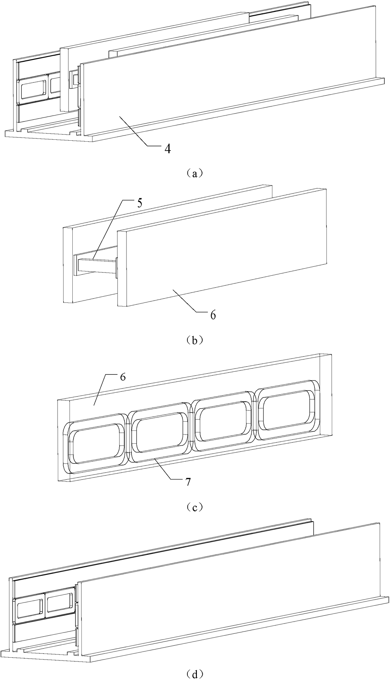
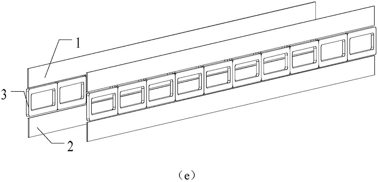
[0030] Specific implementation mode one: combine figure 1 Specifically explaining this embodiment, the high-speed maglev linear electromagnetic propulsion system described in this embodiment is mainly composed of a drive control subsystem and a levitation guidance and propulsion subsystem. The drive control subsystem is mainly composed of a power converter and a controller. The power converter is used to provide driving energy, and the controller is used to control the moving speed of the mover, the position of the mover, and the current of the primary coil 3 . The suspension guidance and propulsion subsystem is mainly composed of stator and mover. The stator is fixed on the ground and is mainly composed of a suspension guiding primary and a propulsion primary; the mover is installed on a skid car 5 and is mainly composed of a cryogenic container 6 and a superconducting coil 7 or a superconducting block. The superconducting coil 7 or a superconducting block The material is i...

specific Embodiment approach 2

[0035] Specific implementation mode two: combination figure 2 Specifically explain this embodiment, the high-speed maglev linear electromagnetic propulsion system described in this embodiment, the high-speed maglev linear electromagnetic propulsion system is mainly composed of a drive control subsystem and a levitation guidance and propulsion subsystem. The drive control subsystem is mainly composed of a power converter and a controller. The power converter is used to provide driving energy, and the controller is used to control the moving speed of the mover, the position of the mover, and the current of the primary coil 3 . The suspension guidance and propulsion subsystem is mainly composed of stator and mover. The stator is fixed on the ground and is mainly composed of a suspension guiding primary and a propulsion primary; the mover is installed on a skid car 5 and is mainly composed of a cryogenic container 6 and a superconducting coil 7 or a superconducting block. The su...

specific Embodiment approach 3

[0040] Specific implementation mode three: combination image 3 Specifically explain this embodiment, the high-speed maglev linear electromagnetic propulsion system described in this embodiment, the high-speed maglev linear electromagnetic propulsion system is mainly composed of a drive control subsystem and a levitation guidance and propulsion subsystem. The drive control subsystem is mainly composed of a power converter and a controller. The power converter is used to provide driving energy, and the controller is used to control the moving speed of the mover, the position of the mover, and the current of the primary coil 3 . The suspension guidance and propulsion subsystem is mainly composed of stator and mover. The stator is fixed on the ground and is mainly composed of a suspension guiding primary and a propulsion primary; the mover is installed on a skid truck 5 and is mainly composed of a permanent magnet array 8 , a shielding conductor plate 9 , and a damping conductor...


PUM


Abstract

The invention relates to a high-speed magnetic levitation linear electromagnetic propulsion system and belongs to the electric motor field. The invention aims to solve the problem of serious magneticflux leakage due to the openness of a magnetic field and the problems of small levitation height, large levitation control difficulty and high requirements for lines of a normal conducting magnetic levitation technology due to large weight of vehicles. The high-speed magnetic levitation linear electromagnetic propulsion system of the invention a primary unit and a secondary unit; the primary unitis mounted on the ground, is of a bilateral structure and is arranged symmetrically on the left side and right side of the secondary unit; air gaps are left between the primary unit and secondary unit; the primary unit comprises a levitation guide primary unit and a propulsion primary unit; each primary structure at each side of the propulsion primary unit includes a primary coil and a primary substrate, wherein the primary coil is fixed at the inner side of the primary substrate; each primary structure at each side of the levitation guide primary unit includes an upper conductor plate and a lower conductor plate, wherein the upper conductor plate and the lower conductor plate are juxtaposed in a vertical direction; the propulsion primary unit is arranged between the upper conductor platesand the lower conductor plates; two columns of magnetic poles of the primary unit are respectively fixed at two sides of a skid; and each column of magnetic poles simultaneously serves as levitationguide magnetic poles and propulsion magnetic poles.

Description

technical field [0001] The invention belongs to the field of motors. Background technique [0002] The existing high-speed maglev linear electromagnetic propulsion system can be divided into two categories: normal conduction type and superconduction type. The constant conduction type is also called the constant conduction magnetic suction type, represented by the German high-speed constant conduction maglev train transrapid, which uses the principle of electromagnetic attraction of ordinary DC electromagnets to suspend the train, and the suspended air gap is small, generally about 10mm. The speed of the conventional high-speed maglev train can reach 400-500km per hour, which is suitable for long-distance rapid transportation between cities. The superconducting magnetic levitation train is also called superconducting magnetic repulsion type, represented by MAGLEV in Japan, which uses the strong magnetic field generated by superconducting magnets, and interacts with the coils...

Claims


Application Information

Patent Timeline
Patent Type & Authority Applications(China)
IPC IPC(8): H02K41/02H02K55/00H02N15/00
CPCH02K41/02H02K55/00H02N15/00Y02E40/60
Inventor 寇宝泉葛庆稳张浩泉
Owner HARBIN INST OF TECH
Why Eureka
Eureka Blog
Learn More