
Limiting mechanism for cable transferring

A limit mechanism and cable transmission technology, which is applied in transportation and packaging, conveying filamentous materials, thin material processing, etc., can solve problems such as cable damage and affecting cable transmission efficiency

Pending Publication Date: 2018-07-20
WUHU HANGTIAN SPECIAL CABLE FACTORY
View PDF6 Cites 2 Cited by
  • Summary
  • Abstract
  • Description
  • Claims
  • Application Information

AI Technical Summary

Problems solved by technology

[0002] During the transmission process of the cable, due to its own long stroke, it will generate a certain vibration force on the cable due to the change of the frequency of the transmission driving force, and the vibration force will cause the cable to swing within a certain range. It is easy to cause damage to the cable. Once damaged, it needs to stop working, which greatly affects the transmission efficiency of the cable.

Method used


Image

  • Limiting mechanism for cable transferring

Examples


Embodiment Construction

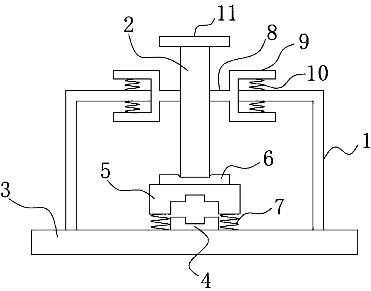
[0025] Specific embodiments of the present invention will be described in detail below in conjunction with the accompanying drawings. It should be understood that the specific embodiments described here are only used to illustrate and explain the present invention, and are not intended to limit the present invention.

[0026] In the present invention, unless otherwise specified, the orientation words included in the term such as "up, down, left, right, front, back, inside and outside" only represent the orientation of the term in the normal use state, or the common name understood by those skilled in the art. , and should not be construed as a limitation of this term.

[0027] see figure 1 The shown limit mechanism for cable transmission, the limit mechanism includes: a base 3, a gantry 1, an upper limit block 5 and a vertical bar 2, the gantry 1 is fixed on the base 3, the The upper beam plate of the gantry 1 is provided with a central through hole, and a lower limit block ...


PUM


Abstract

The invention discloses a limiting mechanism for cable transferring. A portal frame is fixedly connected to a base, and a central through hole is formed in an upper beam plate of the portal frame. A lower limiting block is fixedly connected to the base, and an upper limiting block is coaxially arranged above the lower limiting block. A through groove parallel to the cable transferring direction isformed in the bottom of the upper limiting block, and an upper limiting groove parallel to the cable transferring direction is formed in the groove bottom of the through groove. A lower limiting groove parallel to the upper limiting groove is formed in the upper end of the lower limiting block, and the lower limiting block can be arranged in the through groove in an inlaid mode to enable the upper limiting groove and the lower limiting groove to be in butt joint to form a limiting through hole. A plurality of first springs are arranged between the other surfaces, except the through groove, ofthe bottom end face of the upper limiting block and the base. A driving mechanism for driving a vertical rod to vertically move is connected to the upper end of the vertical rod, and the lower end ofthe vertical rod stretches into a space defined by the portal frame through the central through hole and can make contact with the upper limiting block. The limiting mechanism can effectively controlswing in the cable transferring process.

Description

technical field [0001] The invention relates to an auxiliary device for cable transmission, in particular to a limiting mechanism for cable transmission. Background technique [0002] During the transmission process of the cable, due to its own long stroke, it will generate a certain vibration force on the cable due to the change of the frequency of the transmission driving force, and the vibration force will cause the cable to swing within a certain range. It is easy to cause damage to the cable, and once it is damaged, it needs to stop working, which greatly affects the transmission efficiency of the cable. [0003] Therefore, it is highly desirable to provide a limit mechanism for cable transmission, which can effectively control the swing during cable transmission. Contents of the invention [0004] The object of the present invention is to provide a limit mechanism for cable transmission, which can effectively control the swing of the cable transmission process. [...

Claims


Application Information

Patent Timeline
IPC IPC(8): B65H57/04
CPCB65H57/04B65H2701/34
Inventor 赵明哲何源程奇代少侠
Owner WUHU HANGTIAN SPECIAL CABLE FACTORY
Learn More