Image display device for vehicle
一种影像显示、车辆的技术,应用在车辆部件、静态指示器、运输和包装等方向,能够解决驾驶员无法正常地视觉辨认影像等问题,达到简单构造的效果
- Summary
- Abstract
- Description
- Claims
- Application Information
AI Technical Summary
Problems solved by technology
Method used
Image
Examples
Embodiment 1
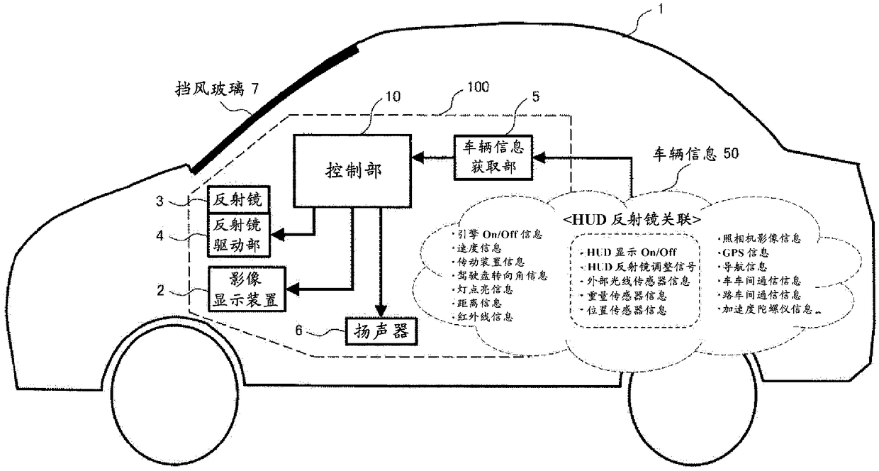
[0079] In Embodiment 1, an example of the mirror adjustment mechanism of the head-up display (HUD) of the present invention will be described, and for easy understanding, it will be described in comparison with a conventional adjustment mechanism.
[0080] Figure 7 It is a figure explaining the conventional mirror adjustment method 1. The image light emitted from the image display device 2 is reflected by the reflector 3 , reflected at the reflective position 70 of the windshield, and enters the driver's eyes 8 , where the driver visually recognizes it as a virtual image 9 . When the positions of the eyes 8 (hereinafter referred to as viewpoints) change as A, B, and C due to the height of the driver, the image light emitted from the video display device 2 may not be incident on each viewpoint, or may be missing even if it can enter. part of the image. In order to cope with this, in the conventional adjustment method 1, a mechanism for rotating the three mirrors by the mirro...
Embodiment 2
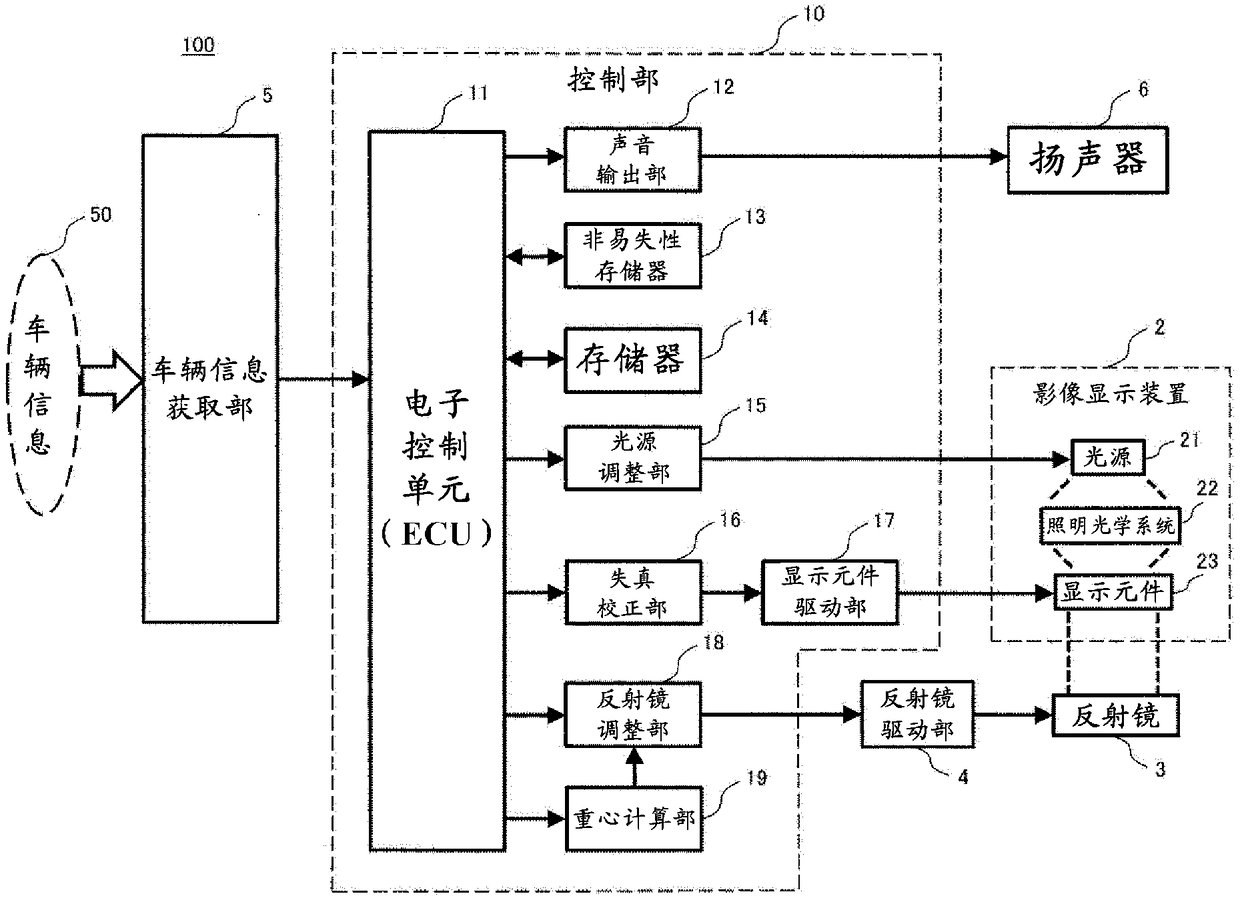
[0109] Embodiment 1 is a configuration in which the driver observes an image to determine the optimum position for mirror adjustment, that is, a manual adjustment method. In contrast, Embodiment 2 is a method of calculating the position of the driver's eyes and automatically adjusting the position of the reflector to an optimal state corresponding thereto. In order to detect the position of the driver's eyes, in this embodiment, the position of the center of gravity of the driver is obtained from the position and weight of the driver, and the position of the eyes is calculated from the position of the center of gravity.
[0110] Thereby, when the driver is replaced by another driver, or when the driving posture of the same driver changes, it is possible to track the position of the eyes of the driver at that time and display an image that is easiest to see. In addition, the adjustment mechanism of the mirror adopts the adjustment methods described in the first embodiment, and ...
Embodiment 3
[0122] In the third embodiment, a configuration in which the entire HUD is moved left and right within the instrument panel in order to move the image display area in the left and right directions will be described. For example, it is necessary to move the display area in the left and right directions in the following cases.
[0123] (1) When the position (viewpoint) of the driver's eyes moves in the left-right direction.
[0124] (2) When the driver's posture (center of gravity position) moves in the left-right direction.
[0125] (3) When the traveling direction of the vehicle changes according to the driving operation (steering wheel operation, direction indicator).
[0126] (4) When the direction of the driver's line of sight changes according to road guidance (left and right turn signs, intersection distance).
[0127] (5) When the direction of the driver's line of sight changes due to an obstacle (a traffic jam, a pedestrian intruding suddenly).
[0128] Changes in th...
PUM
 Abstract
Description
Claims
Application Information
 - R&D
- Intellectual Property
- Life Sciences
- Materials
- Tech Scout
- Unparalleled Data Quality
- Higher Quality Content
- 60% Fewer Hallucinations
Browse by: Latest US Patents, China's latest patents, Technical Efficacy Thesaurus, Application Domain, Technology Topic, Popular Technical Reports.
© 2025 PatSnap. All rights reserved.Legal|Privacy policy|Modern Slavery Act Transparency Statement|Sitemap|About US| Contact US: help@patsnap.com


