
Network entity switching method, terminal, and network entity equipment

A technology of network entities and terminals, applied in the field of communication, which can solve the problems of mobile events unable to meet higher demands, performance degradation, and excessively centralized processing load.

Active Publication Date: 2018-07-13
DATANG MOBILE COMM EQUIP CO LTD
View PDF3 Cites 10 Cited by
  • Summary
  • Abstract
  • Description
  • Claims
  • Application Information

AI Technical Summary

Problems solved by technology

According to the implementation of the existing technology and the above-mentioned multi-connection operation, it is possible for the UE to have no service interruption during the mobility event, but for the multi-connection UE, the anchor point will not be kept unchanged, which will bring many disadvantages to the system The result, such as too long transmission path, too concentrated processing load, etc., thus degrading the performance of the whole system
With the continuous evolution of the network, the mobile events between nodes under the traditional network architecture cannot meet the higher requirements for mobile performance

Method used


Image

  • Network entity switching method, terminal, and network entity equipment
  • Network entity switching method, terminal, and network entity equipment
  • Network entity switching method, terminal, and network entity equipment

Examples


no. 1 example

[0136] Such as Figure 4 As shown, the embodiment of the present invention provides a handover method of a network entity, including:

[0137] Step 41: Receive a new configuration parameter of a second network entity that maintains connection with the terminal sent by the first network entity that maintains connection with the terminal. It is sent by a network entity to configure the instruction information of the anchor point change operation from the first network entity to the second network entity;

[0138] Step 42: When the new configuration parameters take effect, do not perform reset / or reconstruction of underlying transmission, and send an anchor point change confirmation message to the second network entity.

[0139] In this embodiment, the trigger conditions for the new configuration parameters of the terminal to take effect include:

[0140] 1) When the terminal receives the new configuration parameter, it takes effect immediately, and sends a trigger message to n...

no. 2 example

[0145] Embodiments of the present invention provide a network entity handover method, including:

[0146] Step 41: Receive a new configuration parameter of a second network entity that maintains connection with the terminal sent by the first network entity that maintains connection with the terminal. It is sent by a network entity to configure the instruction information of the anchor point change operation from the first network entity to the second network entity;

[0147] Step 42, when the new configuration parameters take effect, do not reset / or rebuild the underlying transmission, and send an anchor point change confirmation message to the second network entity;

[0148] Step 43: Perform data transmission with the second network entity after the second network entity switches the path from the first network entity to the second network entity according to the anchor change confirmation message.

[0149] Specifically, the step of performing data transmission with the seco...

no. 3 example

[0175] Embodiments of the present invention provide a network entity handover method, including:

[0176] Step 41: Receive a new configuration parameter of a second network entity that maintains connection with the terminal sent by the first network entity that maintains connection with the terminal. It is sent by a network entity to configure the instruction information of the anchor point change operation from the first network entity to the second network entity;

[0177] Step 42, when the new configuration parameters take effect, do not reset / or rebuild the underlying transmission, and send an anchor point change confirmation message to the second network entity;

[0178] Step 43: After the second network entity switches the path from the first network entity to the second network entity according to the anchor change confirmation message, exchange service data packets with the first network entity transmission.

[0179] In this embodiment, in step 43, the step of transm...


PUM


Abstract

The invention discloses a network entity switching method, a terminal, and network entity equipment. The network entity switching method comprises steps that new configuration parameters of a second network entity connected with the terminal, which are transmitted by a first network entity connected with the terminal, are received; the new configuration parameters are transmitted by the second network entity according to indication information, which is transmitted by the first network entity, and is configured to switch an anchor point from the first network entity to the second network entity; when the new configuration parameters come into force, resetting and / or rebuilding of underlying transport are / is prevented, and an anchor point switching confirmation message is transmitted to thesecond network entity. By adopting the abovementioned technical scheme, seamless transfer of business data can be guaranteed, and therefore negative influences on a system are improved.

Description

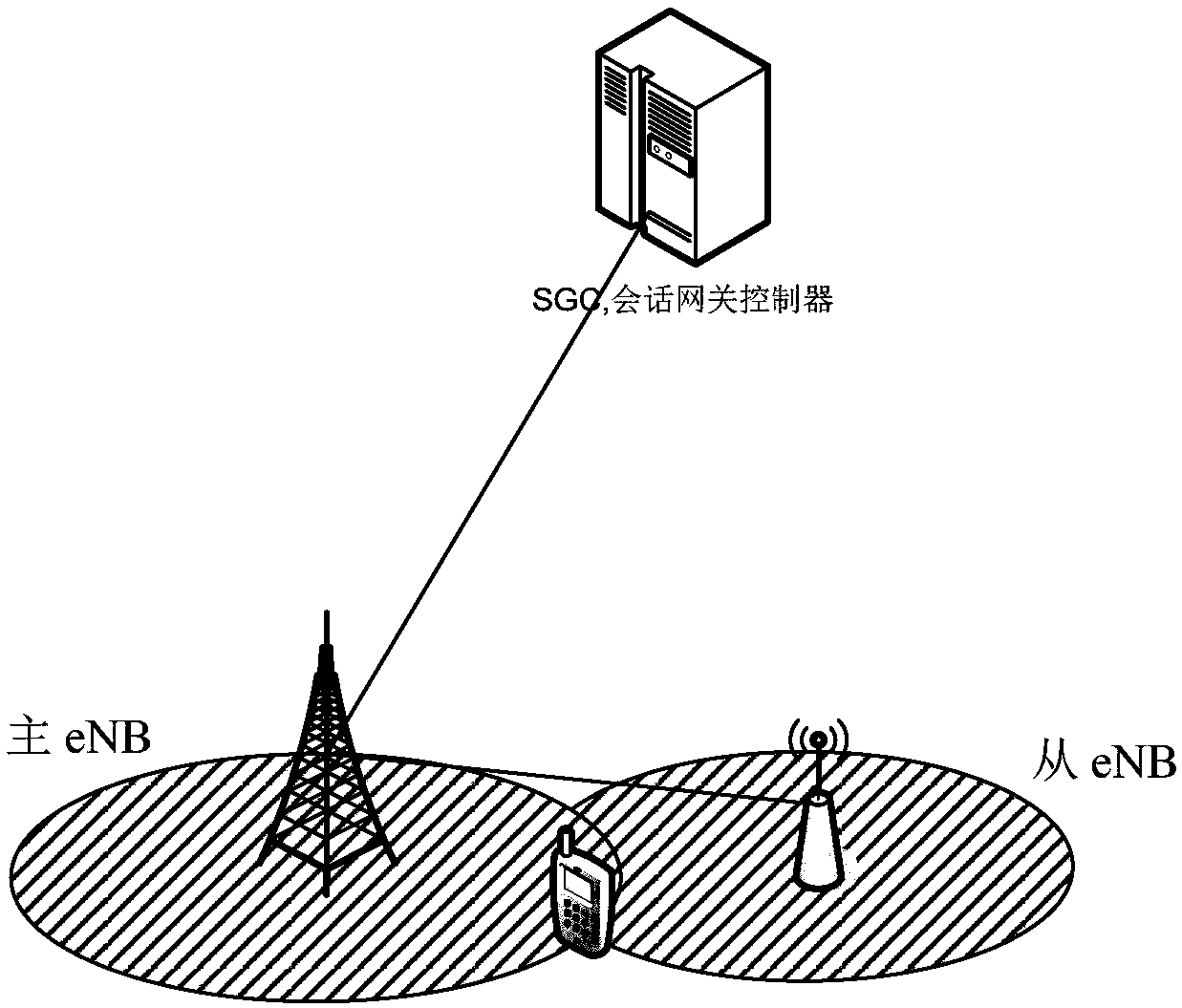
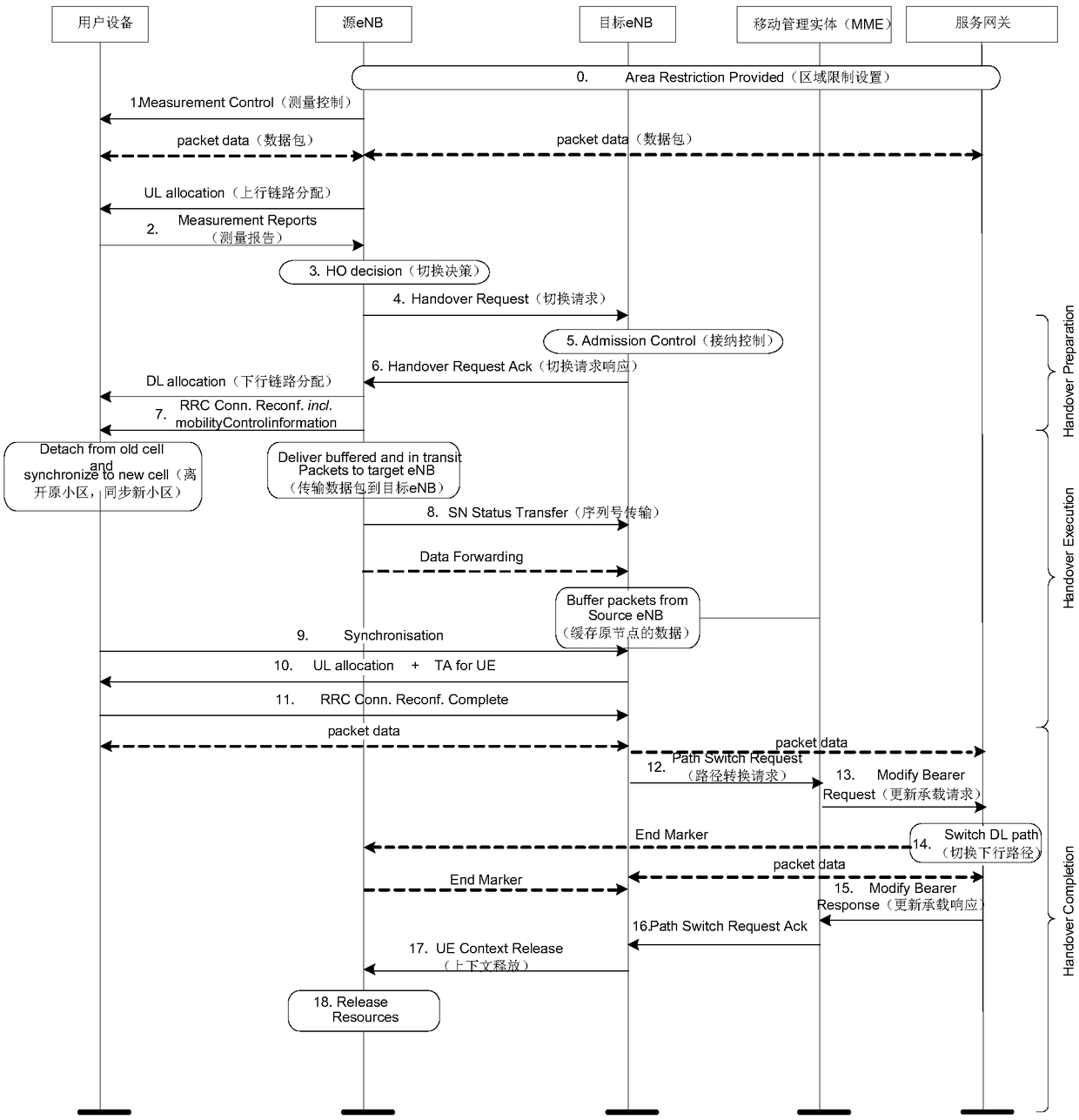
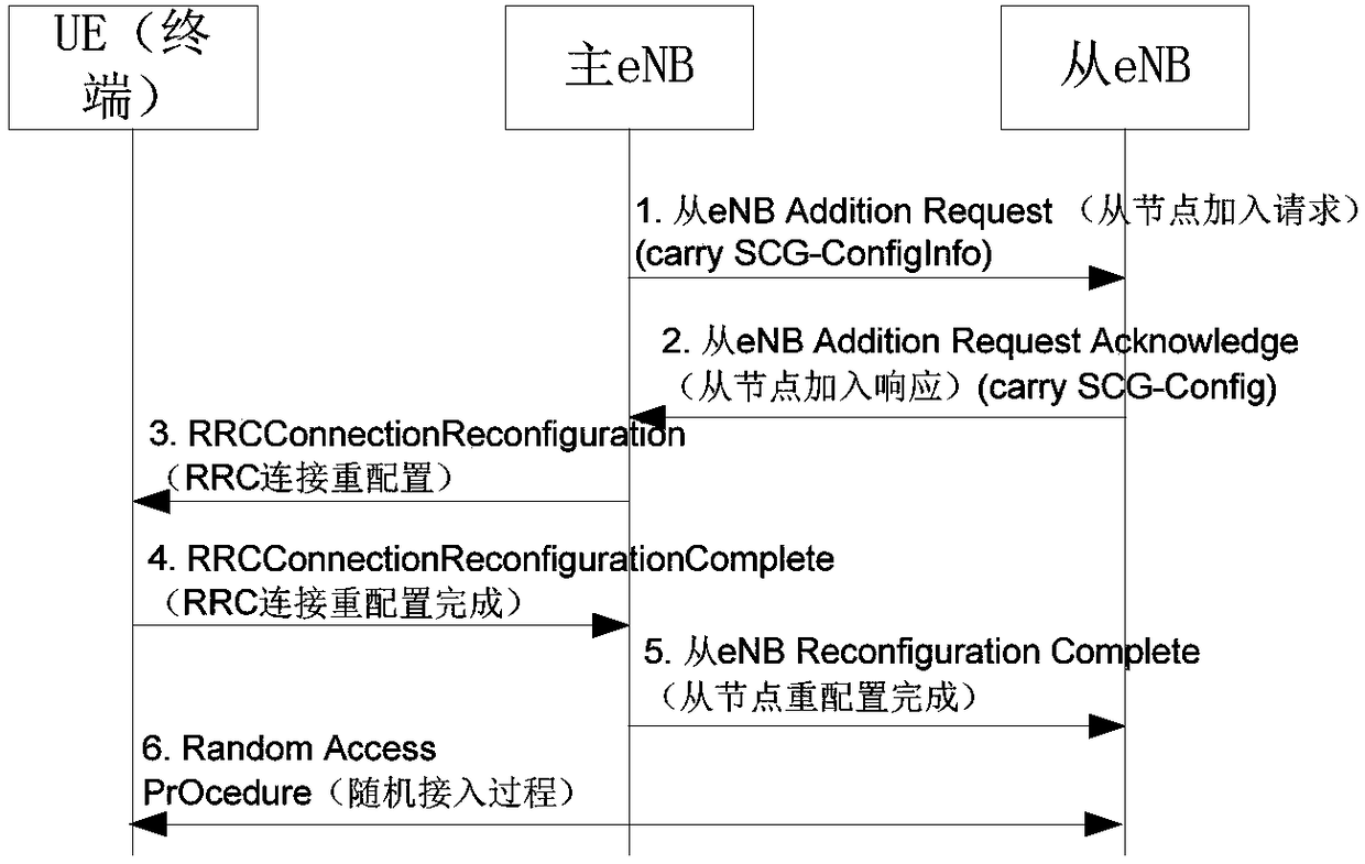
technical field [0001] The present invention relates to the field of communication technology, in particular to a method for network entity switching, a terminal and network entity equipment. Background technique [0002] After the UE (User Equipment) moves to the signal coverage overlap of two network entities (eNB, evolved Node B), the network will trigger a mobility event, such as figure 1 As shown, it is a common dual connectivity mobile scenario, and the UE maintains wireless connections with both the first eNB and the second eNB. [0003] figure 2 For the traditional handover process, including: [0004] 0. Regional restriction setting between source eNB and target eNB, MME (Mobility Management Entity) and SG (Serving Gateway); [0005] 1. The source eNB sends measurement control to the terminal, the terminal transmits data packets with the source eNB, transmits data packets between the source eNB and the serving gateway, and the source eNB performs uplink configur...

Claims


Application Information

Patent Timeline
Patent Type & Authority Applications(China)
IPC IPC(8): H04W36/00H04W36/08H04W36/18
CPCH04W36/0055H04W36/08H04W36/18H04W36/0069H04W76/27H04W28/06H04W36/0072H04W74/0833H04W80/08
Inventor 张大钧许芳丽
Owner DATANG MOBILE COMM EQUIP CO LTD
Learn More