Installation structure capable of being repeatedly demounted

An installation structure and buckle technology, applied in the direction of connecting components, pins, mechanical equipment, etc., can solve the problems of poor strength of the buckle structure, influence on the service life of the components, and reduction of the pull-out force of the buckle, so as to avoid repeated disassembly. , The effect of ensuring assembly accuracy and improving strength

Pending Publication Date: 2018-07-13
CHONGQING PINGWEI AUTO PARTS CO LTD
View PDF0 Cites 2 Cited by
  • Summary
  • Abstract
  • Description
  • Claims
  • Application Information

AI Technical Summary

Problems solved by technology

However, the structural strength of the traditional buckle is poor, and it is easy to fail after repeated disassembly and assembly, and the pull-out force of the buckle is reduced, which affects the assembly effect of the two structural components.
Especially in the automotive field, there are high requirements for the assembly effect between parts. The snap buckle fails after repeated disassembly or assembly or the pull-out force decreases, which not only affects the service life of the parts, but also the assembly parts. Looseness causes abnormal noise and affects product quality; it also affects the safety performance of vehicles in some functional parts

Method used


Image

  • Installation structure capable of being repeatedly demounted
  • Installation structure capable of being repeatedly demounted
  • Installation structure capable of being repeatedly demounted

Examples


Embodiment Construction

[0039] Embodiments of the present invention are described below through specific examples, and those skilled in the art can easily understand other advantages and effects of the present invention from the content disclosed in this specification. The present invention can also be implemented or applied through other different specific implementation modes, and various modifications or changes can be made to the details in this specification based on different viewpoints and applications without departing from the spirit of the present invention.

[0040] It should be noted that terms such as "upper", "lower", "left", "right", "middle" and "one" quoted in this specification are only for the convenience of description and are not intended to be used. To limit the practicable scope of the present invention, the change or adjustment of the relative relationship shall also be regarded as the practicable scope of the present invention without substantially changing the technical conte...


PUM


Abstract

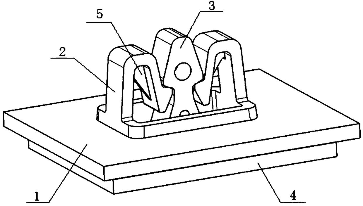
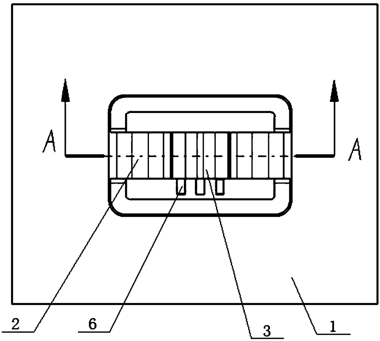
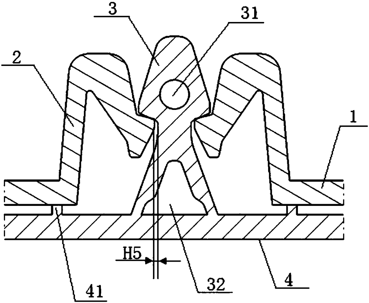
The invention relates to the field of assembly structures, in particular to an installation structure capable of being repeatedly demounted. The installation structure capable of being repeatedly demounted comprises a base and a snap joint. The top of the base is provided with two clamping corners which protrude upwards. The outer side faces of the upper ends of the clamping corners are provided with limiting parts in a protruding manner. The upper ends of the two clamping corners are bent towards the inner sides so that the two limiting parts can be oppositely arranged, a gap for the snap joint to enter or retreat is reserved between the two limiting parts, and the upper end of the snap joint penetrates the base, extends into the gap and is clamped to the two limiting parts. The installation structure capable of being repeatedly demounted has the beneficial effects that by means of the arrangement of the two clamping corners, the snap joint can flexibly and smoothly advance or retreatto coordinate with the limiting parts, meanwhile, the strength of the clamping corners is improved, the situation that the pulling and inserting force is reduced due to the repeated demounting of thesnap joint and the clamping corners is avoided, the strength of the installation structure is improved, and the assembling precision is guaranteed.

Description

technical field [0001] The invention relates to the field of assembly structures, in particular to a repeatedly detachable installation structure. Background technique [0002] When two independent structural parts are assembled, some assembly structures are used to realize the repeated disassembly and assembly between the two parts. For example, the buckle is widely used as a repeated disassembly and assembly structure. However, the structural strength of the traditional buckle is poor, repeated disassembly and assembly are prone to failure, and the pull-out force of the buckle is reduced, which affects the assembly effect of the two structural components. Especially in the automotive field, there are high requirements for the assembly effect between parts. The snap buckle fails after repeated disassembly or assembly or the pull-out force decreases, which not only affects the service life of the parts, but also the assembly parts. Looseness causes abnormal noise and affect...

Claims


Application Information

Patent Timeline
Patent Type & Authority Applications(China)
IPC IPC(8): F16B13/10
CPCF16B13/04F16B13/10
Inventor 田由平周建军高源王卫生
Owner CHONGQING PINGWEI AUTO PARTS CO LTD
Why Eureka
Try Eureka