Slurry mixing and stirring device

A technology of mixing and stirring, applied in the field of ceramic processing, which can solve the problems of reducing the service life of the stirring device, easy sedimentation of pottery clay, and gear damage, etc., and achieve the effect of fast and effective mixing

Active Publication Date: 2019-10-11
山东天广节能科技有限公司
View PDF5 Cites 1 Cited by
  • Summary
  • Abstract
  • Description
  • Claims
  • Application Information

AI Technical Summary

Problems solved by technology

After the pottery clay is dissolved into the stirring device, the pottery clay is easy to settle at the bottom of the whole device, and it is difficult to completely stir the pottery clay with a general stirring rod
[0003] Especially after shutting down at night, the remaining clay in the mixing device will remain in the mixing device. The clay at the bottom of the mixing device is in a state of sedimentation and compaction, and the stirring rod is also buried by the clay. The motor that drives the stirring rod to rotate is forced to start. At this time, the rotation is difficult, which will easily cause the transmission of the motor to be invalid, and then cause the corresponding gear to be damaged. In severe cases, the stirring mechanism of the stirring device will be damaged. If this happens for a long time, the service life of the stirring device will be greatly reduced.

Method used


Image

  • Slurry mixing and stirring device
  • Slurry mixing and stirring device
  • Slurry mixing and stirring device

Examples


Embodiment Construction

[0018] Further detailed explanation through specific implementation mode below:

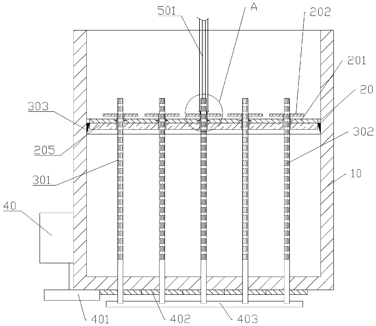
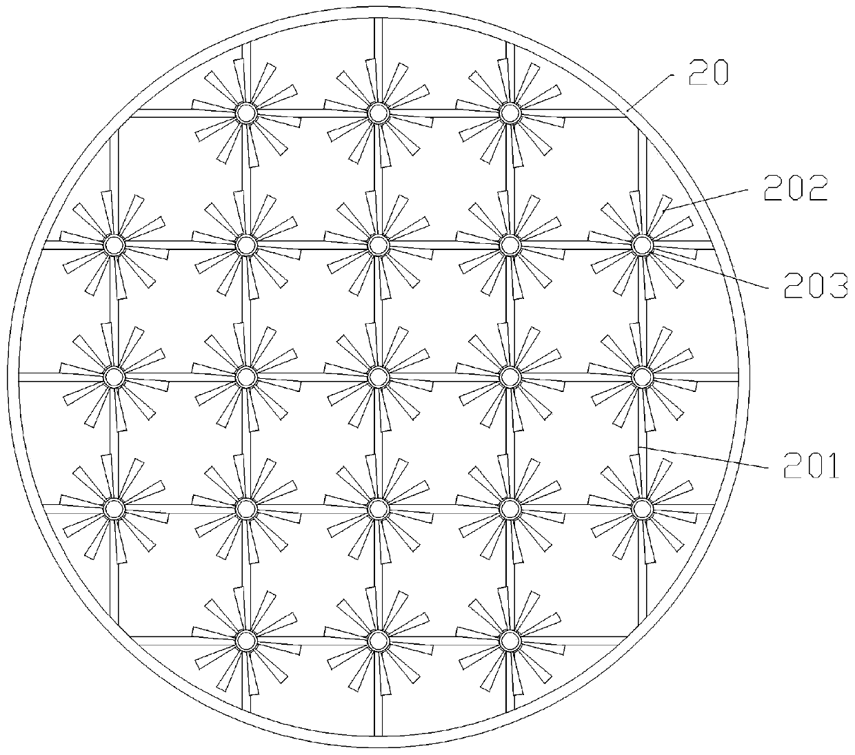
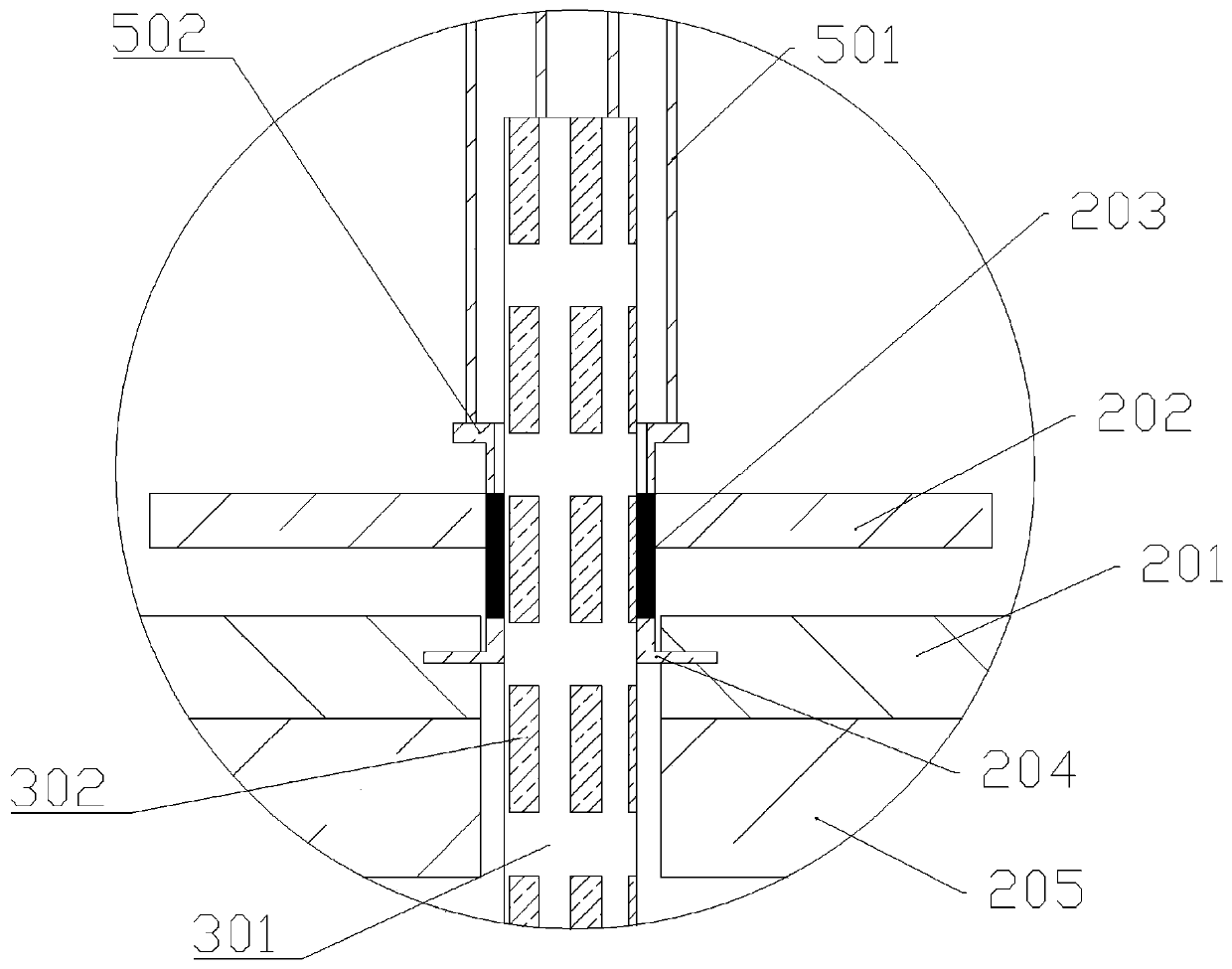
[0019] The reference signs in the drawings of the description include: mixing bucket 10, fixed ring 20, connecting rod 201, blade 202, installation ring 203, boss 204, first blade 205, ejector rod 301, rubber strip 302, second blade 303 , motor 40, driving wheel 401, transmission wheel 402, support seat 403, moving tube 501, connecting block 502.

[0020] The embodiment is basically as attached figure 1 , attached figure 2 And attached image 3 Shown: a slurry mixing and stirring device, including a mixing tank 10, a stirring mechanism and a power mechanism.

[0021] The stirring mechanism includes a fixed ring 20, twenty-one stirring units and several connecting rods 201, the stirring unit includes a hard blade 202 and a mounting ring 203, the outer ring of the fixed ring 20 is in sliding contact with the inner wall of the mixing bucket 10, and the blade 202 is horizontal Welded on the oute...


PUM


Abstract

The invention relates to the field of ceramic machining, and particularly discloses a slurry mixing stirring device. The device comprises a fixed ring, hard blades, mounting rings, rubber strips, ejector rods, a power unit driving the ejector rod to rotate and connecting rods; the outer ring of the fixed ring and the inner wall of a stirring bucket are in sliding contact, the blades are horizontally and fixedly arranged on the outer surfaces of the mounting rings, a boss is arranged at one end of each mounting ring, first grooves in sliding contact with the surfaces of the bosses are arrangedat one ends of the connecting rods, the other ends of the connecting rods are fixedly connected with the inner ring of the fixed ring or provided with second grooves in sliding contact with the surfaces of another bosses, the axes of the connecting rods are perpendicular to the axes of the mounting rings, the sides, away from the blades, of the connecting rods are provided with first blades, the ejector rods are mounted at the bottom of the stirring bucket, the rubber strips are fixedly connected with the side faces of the ejector rods, and the axes of the ejector rods and the axis of the mounting rings are collinear. According to the scheme, pot clay deposited on the bottom of the stirring bucket is rapidly and stably stirred.

Description

technical field [0001] The invention belongs to the field of ceramic processing, and in particular relates to a slurry mixing and stirring device. Background technique [0002] The raw material of ceramics is generally pottery clay, which is a kind of clay used to produce pottery and porcelain. The clay is put into a stirring device and mixed with water to form a slurry, and then ball milled after the slurry is formed. , screening, iron removal, pool storage and other operations. After the pottery clay is dissolved in the stirring device, the pottery clay is easy to settle at the bottom of the whole device, and it is difficult to completely stir the pottery clay with a general stirring rod. [0003] Especially after shutting down at night, the remaining clay in the mixing device will remain in the mixing device. The clay at the bottom of the mixing device is in a state of sedimentation and compaction, and the stirring rod is also buried by the clay. The motor that drives th...

Claims


Application Information

Patent Timeline
Patent Type & Authority Patents(China)
IPC IPC(8): B28C5/08
Inventor 唐其云罗永德李林
Owner 山东天广节能科技有限公司
Why Eureka
Try Eureka