
Rotary type automatic lifting machine

An automatic lifting and rotating technology, applied in the field of mechanical transportation, can solve the problems of low work efficiency and troublesome use, and achieve the effect of improving efficiency and simple structure

Inactive Publication Date: 2018-07-10
南京小脚印网络科技有限公司
View PDF5 Cites 9 Cited by
  • Summary
  • Abstract
  • Description
  • Claims
  • Application Information

AI Technical Summary

Problems solved by technology

At present, most hoists need to wait for the loading tray to lift the material up and then lower it down before continuing to work. The work efficiency is low, and operators need to operate frequently, which is troublesome to use.

Method used


Image

  • Rotary type automatic lifting machine
  • Rotary type automatic lifting machine

Examples


Embodiment Construction

[0016] The present invention will be further explained below in conjunction with the accompanying drawings and specific embodiments. It should be understood that the following specific embodiments are only used to illustrate the present invention and are not intended to limit the scope of the present invention.

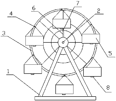
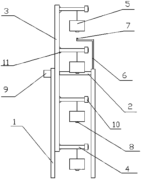
[0017] As shown in the figure, a rotary automatic hoist according to the present invention includes a support 1, and a rotating wheel shaft 2 is arranged between the support 1, and a rotating wheel frame 3 is rotatably connected to the rotating wheel shaft 2. The rotating wheel frame 3 is provided with at least two pivots 4, on which the loading tray 5 is rotatably connected, and the support 1 is also provided with an upward support rod 6, and on the support rod 6 A signal transmitter 7 is provided, and the bottom surface of the loading tray 5 is provided with a signal receiver 8, the positions of the signal transmitter 7 and the signal receiver 8 are corresponding, an...


PUM


Abstract

The invention discloses a rotary type automatic lifting machine. The machine comprises supports, and a rotary wheel axle is arranged between the supports. The rotary wheel axle is rotatably connectedwith a rotary wheel carrier. The rotary wheel carrier is provided with at least two pivots. The pivots are rotatably connected with carrying trays. The supports are also provided with a vertical upward supporting rod. The supporting rod is provided with a signal emitter. The bottom surface of the carrying tray is provided with a signal receiver. Positions of the signal emitters are corresponding to the positions of the signal receivers. The rotary wheel axle is electrically connected with a driving mechanism. The signal receiver is electrically connected with the driving mechanism. The machineis rational in structure. Through rotation of the rotary wheel carrier, continuous rising and falling of the carrying trays are realized, so as to complete circulating operation and effectively improving working efficiency.

Description

technical field [0001] The invention relates to the mechanical transportation industry, in particular to a rotary automatic hoist. Background technique [0002] The hoist is a mechanical device that transports by changing the potential energy, and is widely used in the construction industry, coal mining industry, etc. At present, most hoists need to wait for the loading tray to lift the material up and then lower it down before continuing to work. The work efficiency is low, and operators need to operate frequently, which is troublesome to use. Contents of the invention [0003] In order to solve the above problems, the present invention discloses an automatic rotating hoist, which has a simple structure, can realize the continuous rising and falling of the loading tray, and can realize the automatic rotation and automatic stop of the rotating wheel frame, and is easy to use. [0004] To achieve the above object, technical scheme of the present invention: [0005] A rota...

Claims


Application Information

Patent Timeline
Patent Type & Authority Applications(China)
IPC IPC(8): B65G29/02
CPCB65G29/02
Inventor 赵士恒
Owner 南京小脚印网络科技有限公司
Learn More