High-efficiency switching converter device and method
A switching conversion and boost converter technology, which is applied in the field of power transmission and transformation, can solve the problems of small load change frequency change range, low power factor, and large switching loss of the resonant loop of series-parallel resonant converters, and achieves wide input voltage. Range, low noise sensitivity, and the effect of enhancing dynamic response
- Summary
- Abstract
- Description
- Claims
- Application Information
AI Technical Summary
Problems solved by technology
Method used
Image
Examples
Embodiment 1
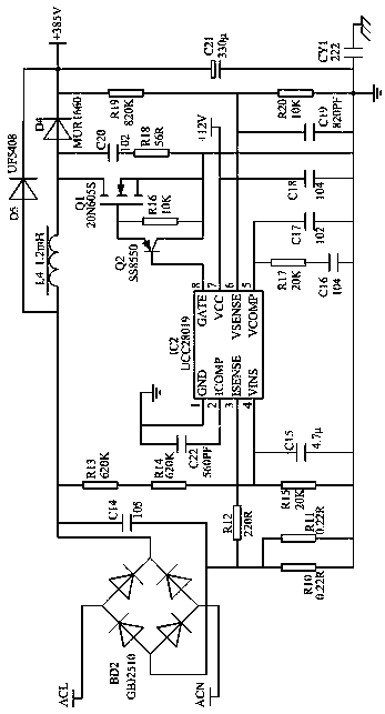
[0020] High-efficiency switching conversion method, the auxiliary power supply adopts a flyback topology, and the chip VIPER22A is a switching device with current control mode pulse width modulation. It integrates a switching tube and a control chip with a wide input voltage range and low standby power consumption. , higher voltage start-up characteristics, and has very complete protection functions such as over-current, over-voltage, under-voltage and over-temperature. Its boost converter control chip is UCC28019, which uses PWM boost circuit. Sampling control of output voltage, sampling control of input voltage, and control method of synchronous input voltage with input current. The power factor reaches 0.995, the total harmonic distortion rate is less than 3%, the noise sensitivity is small, the starting current is low, and it has soft start, undershoot Complete protection functions such as voltage lock, input power-down protection, output overvoltage protection, open-loop p...
Embodiment 2
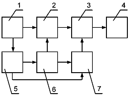
[0022] The equipment used in the high-efficiency switching conversion method comprises: AC input terminals, the AC input terminals 1 are electrically connected to the boost converter 2 and the auxiliary power supply 5, and the boost converter is electrically connected to A resonant converter 3, the resonant converter is connected to the output terminal 4, the auxiliary power supply is respectively connected to the boost converter control circuit 6 and the resonant converter control circuit 7, and the boost converter control circuit is respectively connected to the step-up converter A voltage converter and a resonant converter control circuit, the resonant converter control circuit is connected to the resonant converter.
[0023] Example 2:
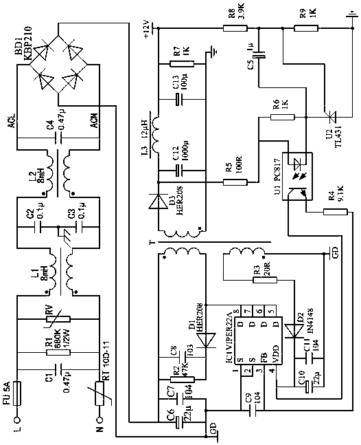
[0024] According to the equipment used in the high-efficiency switching conversion method described in Embodiment 1, the auxiliary power supply is in a flyback control mode, and the control chip adopts a VIPER22A integrated with a PWM cont...
Embodiment 3
[0026] According to the equipment used in the high-efficiency switching conversion method described in Embodiment 1, the switching tube MOSFET of the boost converter is 20N605S of Infineon, and the inductance of the boost converter is a sendust magnetic ring 47 *24*18 enameled wire self-winding, the boost converter control circuit chip is UCC28019 of TI company, the switching tube MOSFET of the resonant converter is W20NB50 of ST company, the high frequency of the resonant converter The transformer is self-winding with ferrite core EE42 enameled wire. The leakage inductance of the resonant converter is self-winding with 39.9*24.1*14.5 enameled wire. The control circuit chip of the resonant converter is ST company. The L6599N.
[0027] All of its circuits are connected by wires, and those with the same names and labels in each figure are connected together; refer to the attached figure 1 , the AC voltage of 70V~265VAC is used as the input of the boost converter 2 and the auxil...
PUM
 Abstract
Description
Claims
Application Information
 - R&D Engineer
- R&D Manager
- IP Professional
- Industry Leading Data Capabilities
- Powerful AI technology
- Patent DNA Extraction
Browse by: Latest US Patents, China's latest patents, Technical Efficacy Thesaurus, Application Domain, Technology Topic, Popular Technical Reports.
© 2024 PatSnap. All rights reserved.Legal|Privacy policy|Modern Slavery Act Transparency Statement|Sitemap|About US| Contact US: help@patsnap.com


