Pull-rod-self-bucking type motor fan cover

A technology of pull rod and wind cover, which is applied in the field of pull rod self-locking motor wind cover, which can solve the problems of increased vibration value and noise value of the motor, enlarged vibration and noise of the wind cover, and long process time, so as to reduce vibration and noise, Easy to install and disassemble, and the outer circle of the windshield is compact

Active Publication Date: 2018-07-06
WOLONG ELECTRIC GRP CO LTD
View PDF5 Cites 0 Cited by
  • Summary
  • Abstract
  • Description
  • Claims
  • Application Information

AI Technical Summary

Problems solved by technology

[0002] At present, the motor field adopts the method of fixing the front and rear end covers with tie rods. Because of its simple installation and maintenance, strong stability, etc., the application occasions continue to expand; the wind cover used for the self-fan cooling system is basically fixed to the rear end cover with screws. The way of the end face of the stand is troublesome to install and disassemble, and the process takes a long time. In addition, because the screw installation on the end cover stand requires a certain height, the outer circle of some windshields is higher than the center height of the motor. In order to avoid the windshield of the horizontal motor from colliding with the ground The improved trimming makes the appearance of the windshield and the motor poor, and the vibration and noise of the motor are transmitted. The vibration and noise of the windshield that is in direct contact with the end cover will be further enlarged at the same time, which will increase the vibration and noise of the motor and reduce the motor. overall quality

Method used


Image

  • Pull-rod-self-bucking type motor fan cover
  • Pull-rod-self-bucking type motor fan cover
  • Pull-rod-self-bucking type motor fan cover

Examples


Embodiment Construction

[0023] The technical solution of the present invention will be further described in detail below in conjunction with the accompanying drawings.

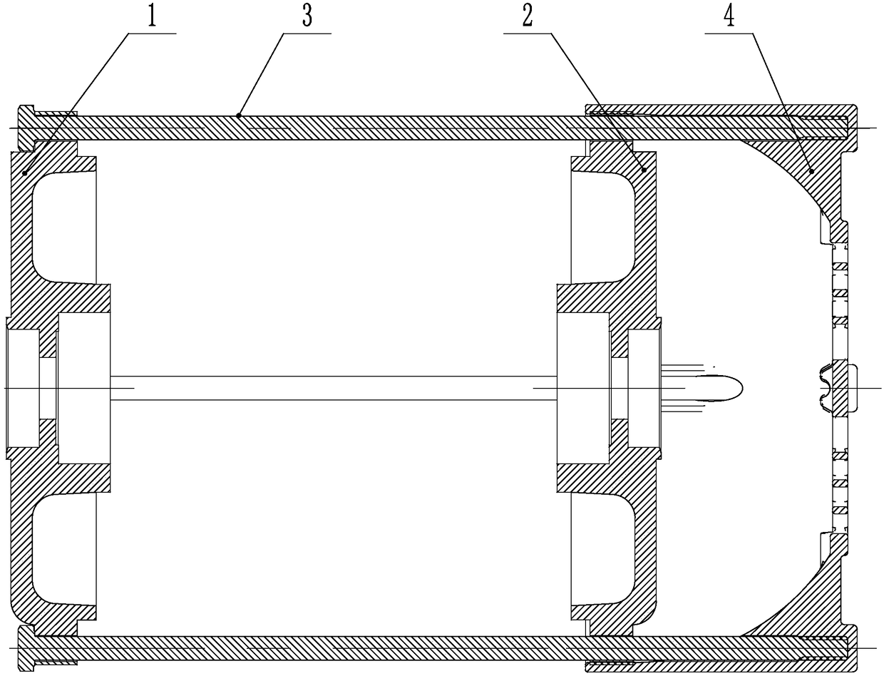
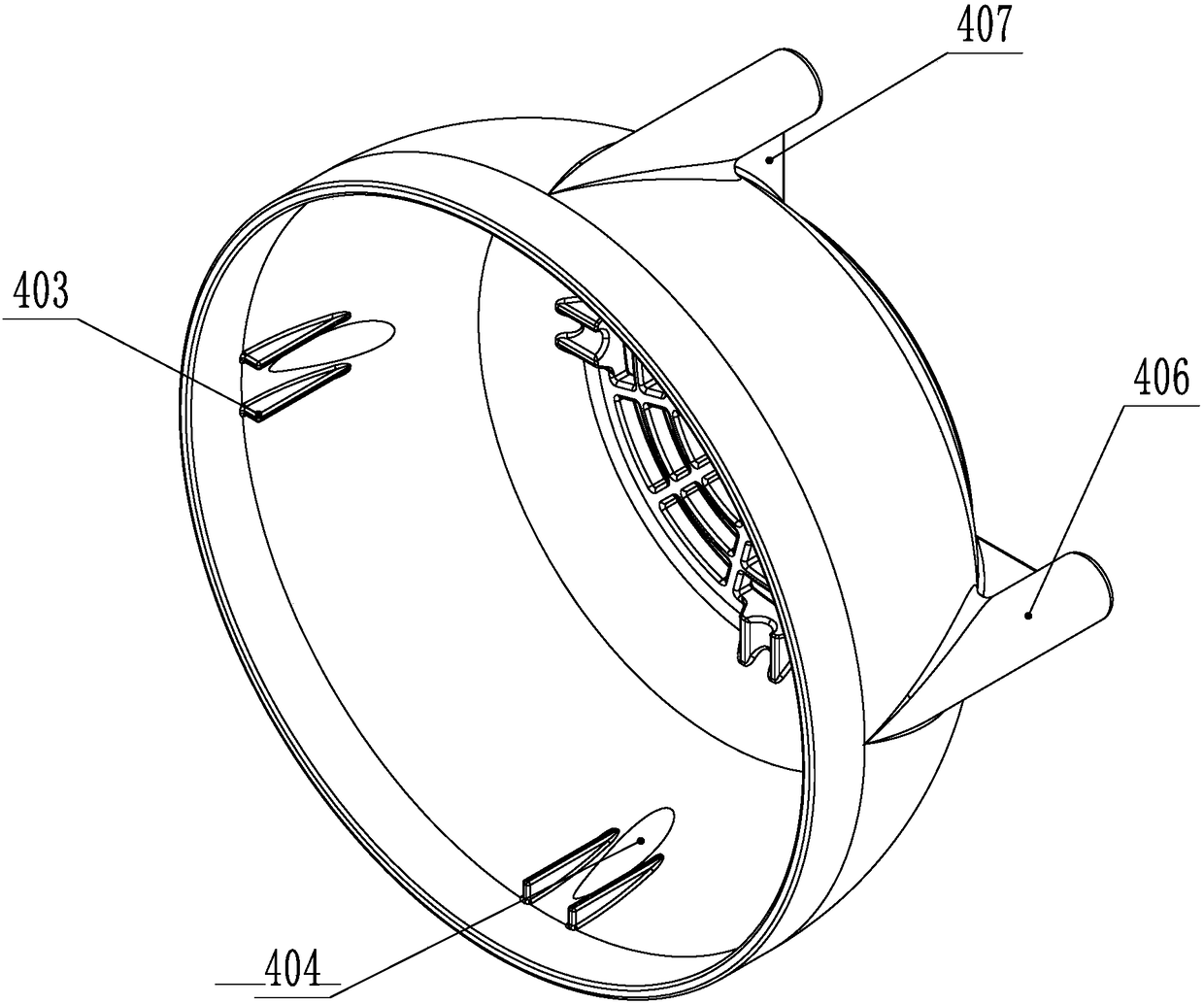
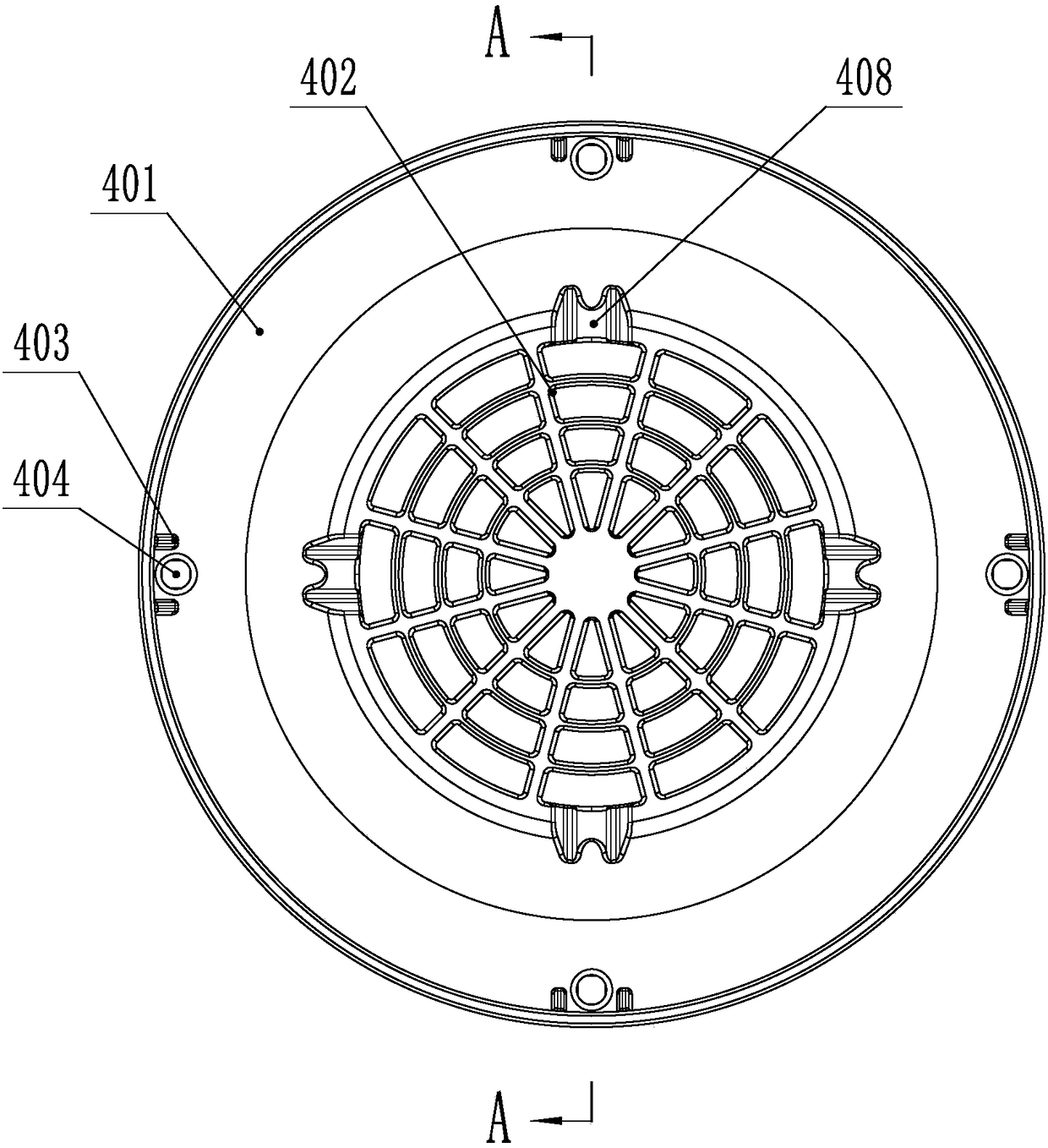
[0024] Such as Figure 1-4 As shown, the pull rod self-locking motor wind cover, the wind cover 4 includes a wind cover ring 401 and an air inlet window 402, the pull rod 3 is screwed into the threaded hole of the rear end cover 2 from the motor front end cover 1, and the rear end of the wind cover ring 401 is in the inner wall. There are four tie rod holes 404 evenly distributed around the upper part for the pull rod 3 to enter, and each tie rod hole 404 is provided with a self-fastening piece 405 that automatically realizes fastening after the tie rod 3 enters, and the tie rod 3 passes through the threaded hole of the rear end cover 2 Then it enters the pull rod hole 404 forward, and is automatically fastened and fixed by the self-fastening piece 405 .

[0025] In order to judge whether the windshield 4 is installed in place, a po...


PUM


Abstract

The invention, which relates to the motor field, provides a pull-rod-self-bucking type motor fan cover. A common fan cover is in contact with an end cover directly; and the vibration value and the noise value of the motor are increased by fan cover vibration and noises, so that the overall quality of the motor is reduced. The pull-rod-self-bucking type motor fan cover comprises a fan cover ring and an inlet window. A pull rod is screwed into a thread hole formed at a rear end cover from a front end cover of a motor; a plurality of pull rod holes for pull rod entrance are formed in the rear part in the inner wall of the fan cover ring; and a self-buckling piece for automatic tight buckling of the pull rod after entrance is arranged in each pull rod hole. The pull rod passes through the thread hole of the rear end cover, moves forward, and enters the pull rod hole and then is buckled and fixed automatically by the self-buckling pieces. When the fan cover is installed, the pull rod holesof the fan cover are aligned at the pull rod for insertion; and the self-buckling pieces and the pull rod are in an automatic buckling and fixation relationship. On the basis of the self-buckling piece mode, fixation between the fan cover and the pull rod is realized quickly to realize installation and fixation of the fan cover and the motor. When the fan cover is dismounted, the rear end of the fan cover ring is hooked and is pulled back to realize separation of the self-buckling pieces from the pull rod. Therefore, quick dismounting is realized; and the vibration and the noises can be effectively reduced.

Description

technical field [0001] The invention relates to the field of motors, in particular to a pull rod self-locking type motor fan cover. Background technique [0002] At present, the motor field adopts the method of fixing the front and rear end covers with tie rods. Because of its simple installation and maintenance, strong stability, etc., the application occasions continue to expand; the wind cover used for the self-fan cooling system is basically fixed to the rear end cover with screws. The way of the end face of the stand is troublesome to install and disassemble, and the process takes a long time. In addition, because the screw installation on the end cover stand requires a certain height, the outer circle of some windshields is higher than the center height of the motor. In order to avoid the windshield of the horizontal motor from colliding with the ground The improved trimming makes the appearance of the windshield and the motor poor, and the vibration and noise of the m...

Claims


Application Information

Patent Timeline
Patent Type & Authority Applications(China)
IPC IPC(8): H02K5/20H02K5/24H02K15/14
CPCH02K5/20H02K5/24H02K2205/09H02K2213/03
Inventor 杭文龙王自贵孙军建张小康
Owner WOLONG ELECTRIC GRP CO LTD
Why Eureka
Try Eureka