
Adaptive positioning device for ground-penetrating radar antennas in shield tunnels

A position adjustment device, ground penetrating radar technology, applied in the direction of antenna support/installation device, antenna, electrical components, etc., can solve the problem of unresolved problems such as the lack of coordination between the shielded antenna and the moving vehicle, poor adhesion of the segment, and incoordination, etc. problems, to achieve the effects of improving operating efficiency, avoiding personnel safety and instrument damage, and reducing production costs

Pending Publication Date: 2018-07-06
CENT SOUTH UNIV +1
View PDF2 Cites 8 Cited by
  • Summary
  • Abstract
  • Description
  • Claims
  • Application Information

AI Technical Summary

Problems solved by technology

Both of the above two known patents involve the operation of fixing the position and adjusting the height of the ground penetrating radar. Although the operation is convenient and suitable for long-term data collection, which liberates manpower to a certain extent, it does not solve the problem of cooperation between the shielded antenna and the moving vehicle. Problems such as inconsistency, poor adhesion between the shielded antenna and the segments outside the vault, etc.

Method used


Image

  • Adaptive positioning device for ground-penetrating radar antennas in shield tunnels
  • Adaptive positioning device for ground-penetrating radar antennas in shield tunnels
  • Adaptive positioning device for ground-penetrating radar antennas in shield tunnels

Examples


Embodiment Construction

[0025] The following will clearly and completely describe the technical solutions in the embodiments of the present invention with reference to the accompanying drawings in the embodiments of the present invention. Obviously, the described embodiments are only some, not all, embodiments of the present invention. Based on the embodiments of the present invention, all other embodiments obtained by persons of ordinary skill in the art without making creative efforts belong to the protection scope of the present invention.

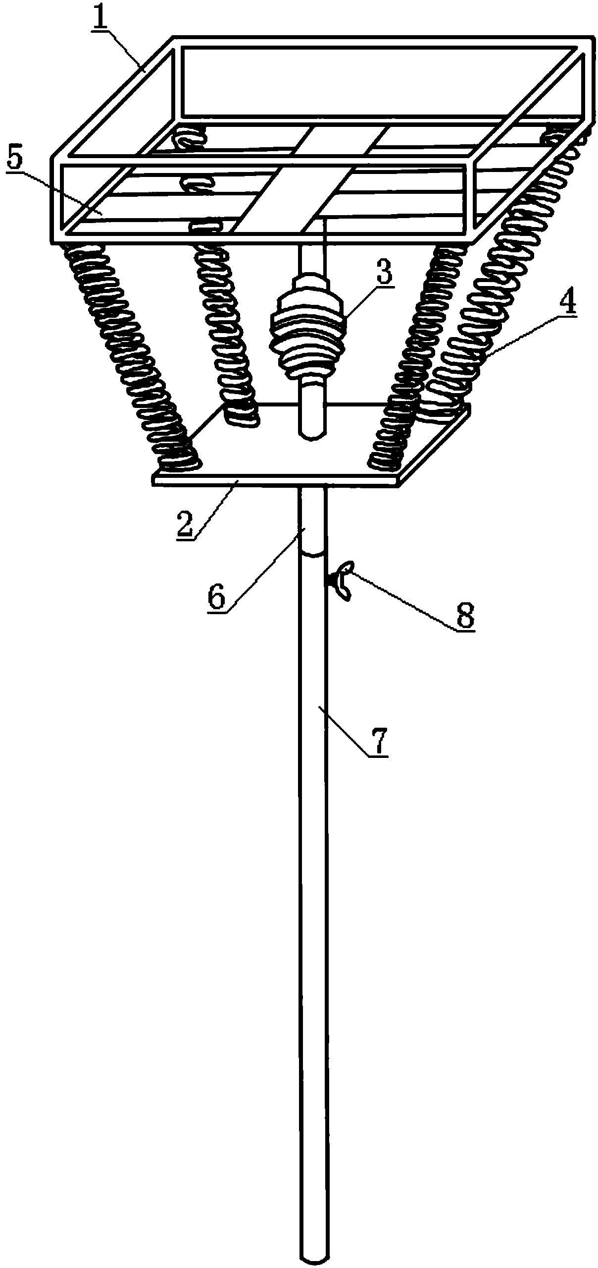
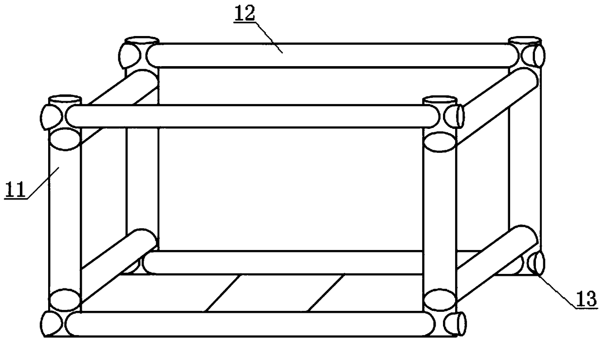
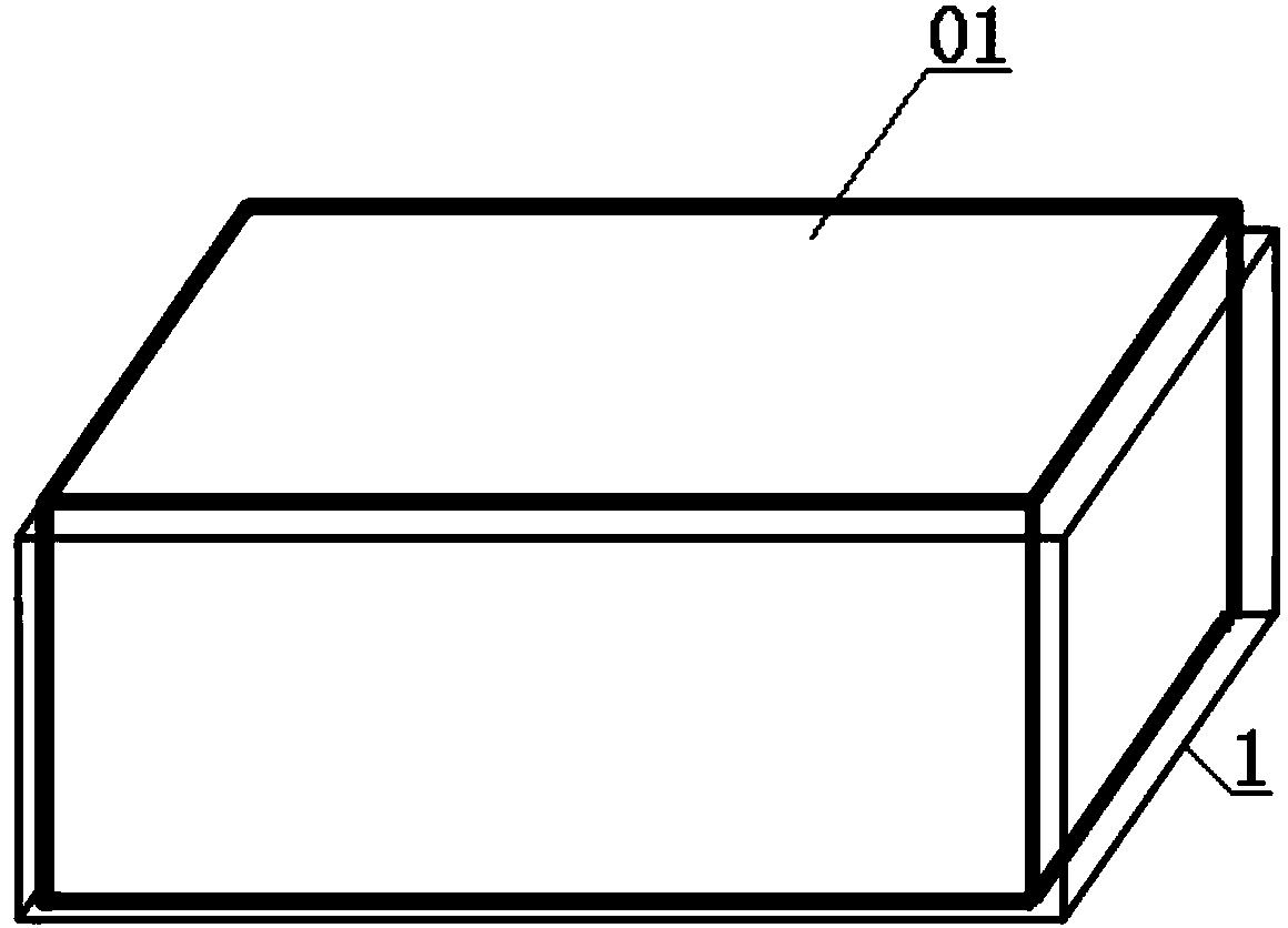
[0026] see Figure 1-Figure 4 , an adaptive positioning device for a ground penetrating radar antenna for a shield tunnel, comprising a cartridge 1 for placing a shielded antenna 01, a support base 2 arranged below the cartridge 1, and a support plate vertically passing through the support Base plate 2 and a support rod whose top end is fixedly connected with the lower bottom surface of the cartridge.

[0027] The cartridge 1 is a telescopic expansion structu...


PUM


Abstract

The invention provides an adaptive positioning device for ground-penetrating radar antennas used in shield tunnels. The adaptive positioning device a clamp box used for placing shield antennas, a support base plate arranged under the clamp box and a support rod vertically penetrating the support base plate with the top fixedly connected with the lower bottom surface of the clamp box; the clamp boxhas an extensible structure and is provided with an elastic tightening belt at the bottom, the support rod is of an extensible structure and is provided with a ball universal joint on the upper portion, the ball universal joint is located between the clamp box and the support base plate so as to allow the clamp box to rotate optionally by taking the ball universal joint as an axis, multiple high-strength springs are arranged on the periphery of the ball universal joint with two ends respectively connected on the clamp box and the support base plate, and the support function of the rotating clamp box and the inner shield antennas is realized. By the arrangement, the shield antennas and arc segments at any positions can be assuredly kept close, and data acquisition quality, operation efficiency and security coefficient in grouting detection after shielding of tunnel walls.

Description

technical field [0001] The invention relates to the technical field of shield tunnel segment detection equipment, in particular to an adaptive positioning device for a ground-penetrating radar antenna for a shield tunnel. Background technique [0002] Ground-penetrating radar, also known as ground-penetrating radar or ground-penetrating radar, is a non-destructive geophysical detection method that uses high-frequency electromagnetic waves to determine the distribution of underground media. At present, this technology is widely used in grouting behind the wall of subway shield tunnels Through the test and detection of the grouting body in the radial direction and length direction of the tunnel and the gap between the grouting body and the tunnel segment (that is, the thickness and defects of the grouting body), it is possible to quickly grasp the grouting in the tunnel The filling condition and construction quality between the sheet and the soil provide an important basis for...

Claims


Application Information

Patent Timeline
Patent Type & Authority Applications(China)
IPC IPC(8): H01Q1/20H01Q3/02
CPCH01Q1/20H01Q3/02
Inventor 张彬梁晓东王文杰张四全周延栋谢平刘妙群
Owner CENT SOUTH UNIV
Learn More