
Zoom lens unit

A zoom lens and lens technology, which is applied in the field of zoom lenses, can solve the problems of focusing on objects at very close distances, large loads on computing chips, and distortion of resolution, etc., to achieve increased curvature, increased back focus margin space, and improved aberrations Effect

Active Publication Date: 2018-07-06
JIAXING ZHONGRUN OPTICAL TECH
View PDF2 Cites 7 Cited by
  • Summary
  • Abstract
  • Description
  • Claims
  • Application Information

AI Technical Summary

Problems solved by technology

The mainstream lens imaging solutions use distortion correction to reduce the impact of distortion, but the correction will cause distortion of the resolution, the effect is not good, and it will bring a large load to the computing chip
[0004] Because the distance difference between macro and normal shooting is too large, ordinary lenses cannot focus on extremely close objects, and a macro lens group needs to be added to the front of the lens, and even after obtaining images in this way, it is often necessary to adjust the focus greatly Groups can achieve a clear picture, and the picture will have serious field curvature. Almost no lens can achieve the same image quality as a long-distance shooting in a macro situation.

Method used


Image

  • Zoom lens unit
  • Zoom lens unit
  • Zoom lens unit

Examples


Embodiment 1

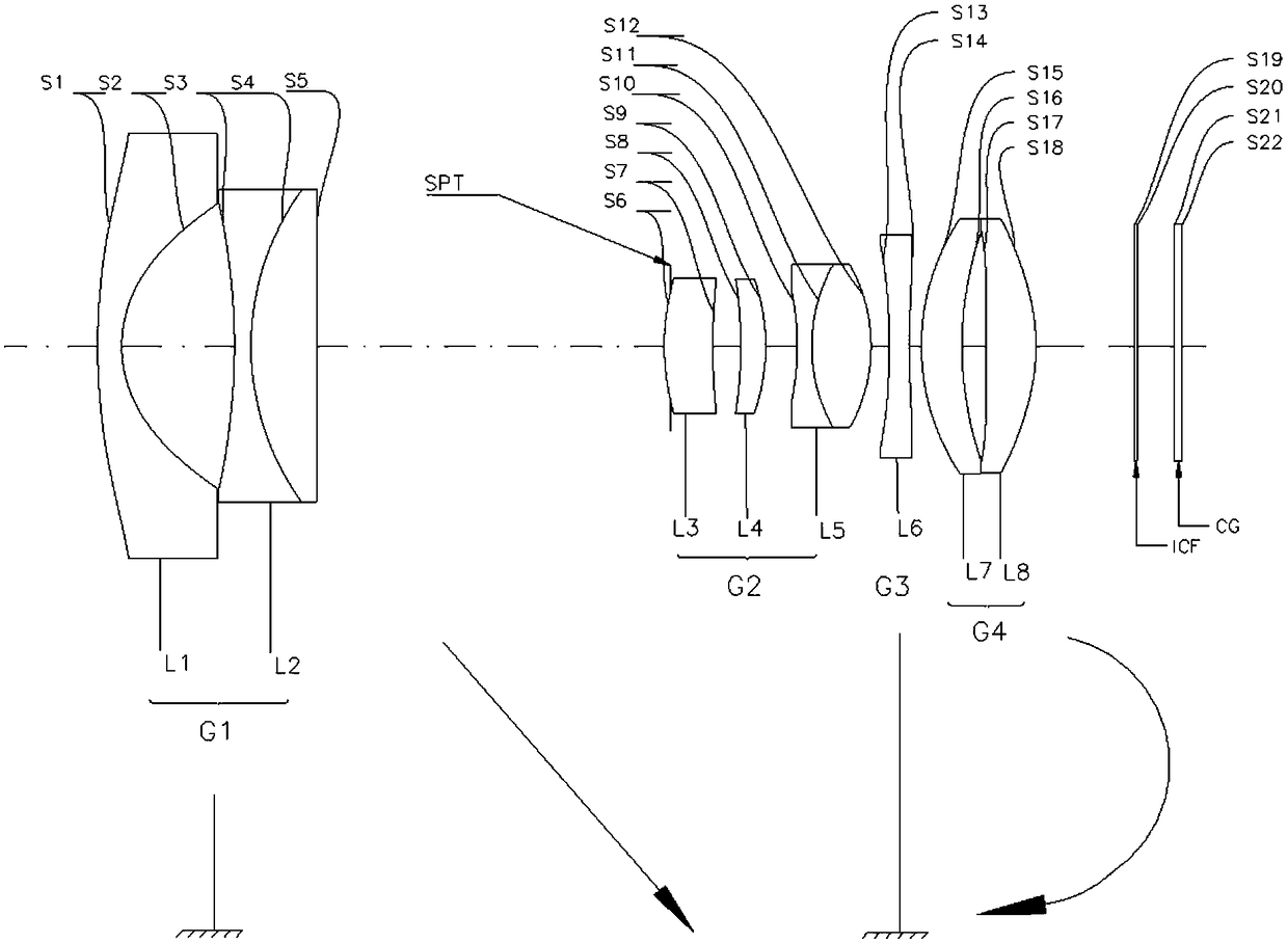
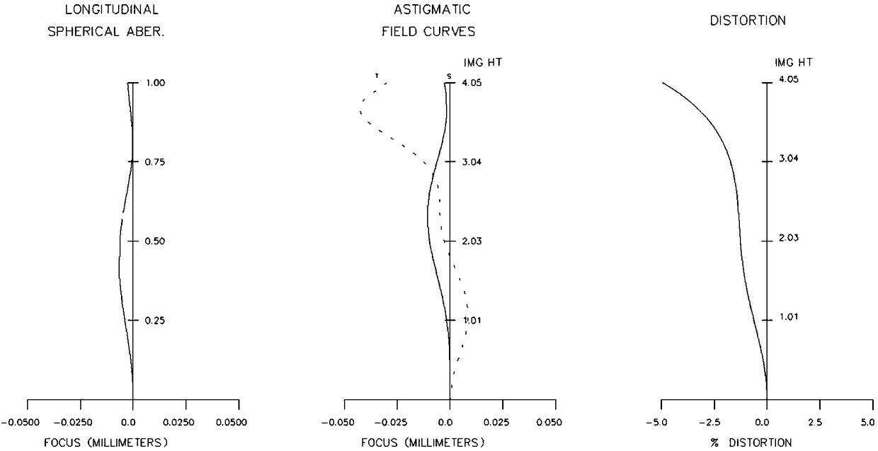
[0042] Such as figure 1 As shown, it is a zoom lens related to this embodiment, which specifically includes: a fixed lens group G1 with negative refractive power, an aperture stop SPT, a zoom lens group G2 with positive refractive power, and a lens group with negative refractive power. The fixed lens G3, the focusing lens group G4 with positive refractive power, and the filter ICF perform zooming from the wide-angle end to the telephoto end by moving the zoom lens group along the optical axis from the image side to the object side. The focus lens group moves along the optical axis to perform correction and focus adjustment of image plane variation accompanying magnification.

[0043] The fixed lens group G1 includes: a first lens L1 with negative refractive power and double-sided aspheric surfaces, and a first cemented lens L2 with positive refractive power.

[0044] The zoom lens group G2 includes: a third lens L3 with positive refractive power and double aspherical surfaces...

Embodiment 2

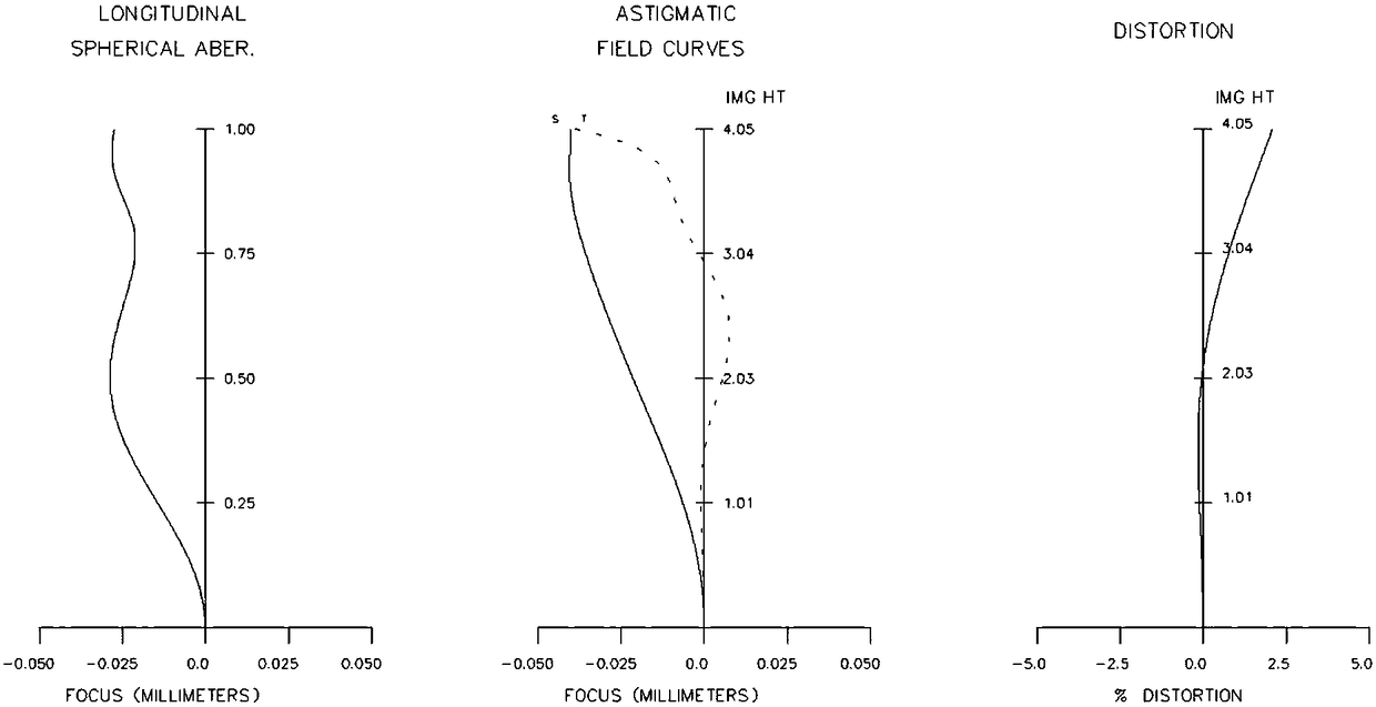
[0060] Such as Figure 4 As shown, compared with Embodiment 1, the focusing lens group G4 in this embodiment adopts the seventh lens L7 with positive refractive power.

[0061] In a state where the fixed lens group and the fixed lens are fixed, the zoom lens group is moved from the object side to the image side along the optical axis to perform zooming from the wide-angle end to the telephoto end. , by moving the focusing lens group along the optical axis, correction and focusing of image plane variation accompanying magnification are performed.

[0062] Various numerical data about the zoom lens of Example 2 are shown below.

[0063] EFL=3.95 wide-angle end~7.90 intermediate focus position~11.40 telephoto end

[0064] FNo=2.52 wide-angle end~3.91 intermediate focus position~4.57 telephoto end

[0065] Table 4 shows the structural parameters of the lens of Example 2; Table 5 shows the zoom parameters of the lens of Example 2; Table 6 shows the aspheric coefficient of the le...


PUM


Abstract

A zoom lens unit comprises, from the objective side to the image side, a fixed lens group of negative focal power, an aperture diaphragm, a zoom lens group of positive focal power, a fixed lens of negative focal power, a focus lens group of positive focal power and an optical filter; the zoom lens group is moved along an optical axis from the image side to the objective side so as to achieve zooming from a wide end to a telescopic end, the focus lens group is moved along the optical axis to achieve variable image side correction and focusing with zooming. The zoom lens unit has the advantagesof light weight, small size, wide angle, multiple zooming in short range, zero distortion, macro shooting and the like.

Description

technical field [0001] The invention relates to a technology in the field of optical devices, in particular to a zoom lens with small volume, 4K image quality and macro function. Background technique [0002] Since the design of the zoom lens is very limited, in order to take into account the performance of each magnification and obtain a better resolution, zooming is usually achieved by the cooperation of the zoom group and the focus group. The number of lenses is often large, and the accumulation of lenses and the travel allowance of the moving amount will cause the size of the lens to become longer. In order to compress the length, the small magnification zoom lens usually adopts a two-group zoom structure, and the rear group often has a large number of lenses stacked, so the compression method is not effective; because of the pursuit of wide-angle, the first group of lenses has a larger aperture, and the traditional second group structure The second group A group of mov...

Claims


Application Information

Patent Timeline
IPC IPC(8): G02B15/16
CPCG02B15/16
Inventor 厉冰川陈三忠尚洁阳盛亚茗张平华
Owner JIAXING ZHONGRUN OPTICAL TECH
Learn More