
Silencing machine cabinet of high-speed centrifugal-type fan

A high-speed centrifugal and fan technology, used in machines/engines, mechanical equipment, non-variable-capacity pumps, etc., can solve the problems of a single sound-absorbing material, affecting physical and mental health, and living troubles for residents, so as to improve sound insulation and noise reduction. ability, reduce aerodynamic noise, and enhance the effect of sound absorption and sound insulation

Inactive Publication Date: 2018-07-06
NANJING CIGU TECH CORP LTD
View PDF4 Cites 1 Cited by
  • Summary
  • Abstract
  • Description
  • Claims
  • Application Information

AI Technical Summary

Problems solved by technology

The cabinet structure of the fan is divided into two parts: the main cabinet and the electric control cabinet. The running speed of the main engine in the main cabinet is about 15000 rpm to 40000 rpm. Without noise control, it will cause troubles to the work of on-site workers and the lives of nearby residents, and in severe cases, it will affect people's physical and mental health
[0003] The shape of the existing fan cabinet is generally hexahedron, the inlet filter and the exhaust port are distributed in the main cabinet, the cabinet door is welded with cold-rolled plate, and filled with a single sound-absorbing material, it is difficult to absorb or block the high frequency generated by the fan Noise, the noise reduction effect is not ideal

Method used


Image

  • Silencing machine cabinet of high-speed centrifugal-type fan
  • Silencing machine cabinet of high-speed centrifugal-type fan
  • Silencing machine cabinet of high-speed centrifugal-type fan

Examples


Embodiment Construction

[0020] The present invention will be further described below in conjunction with the accompanying drawings.

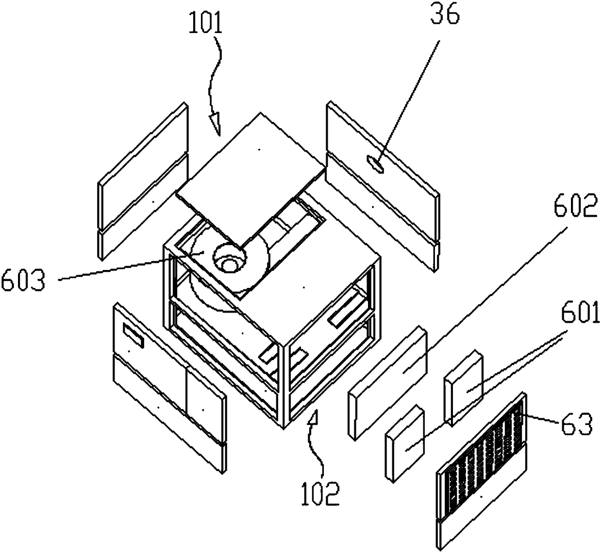
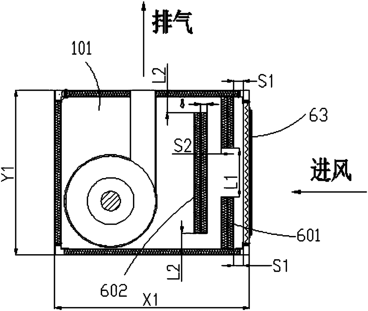
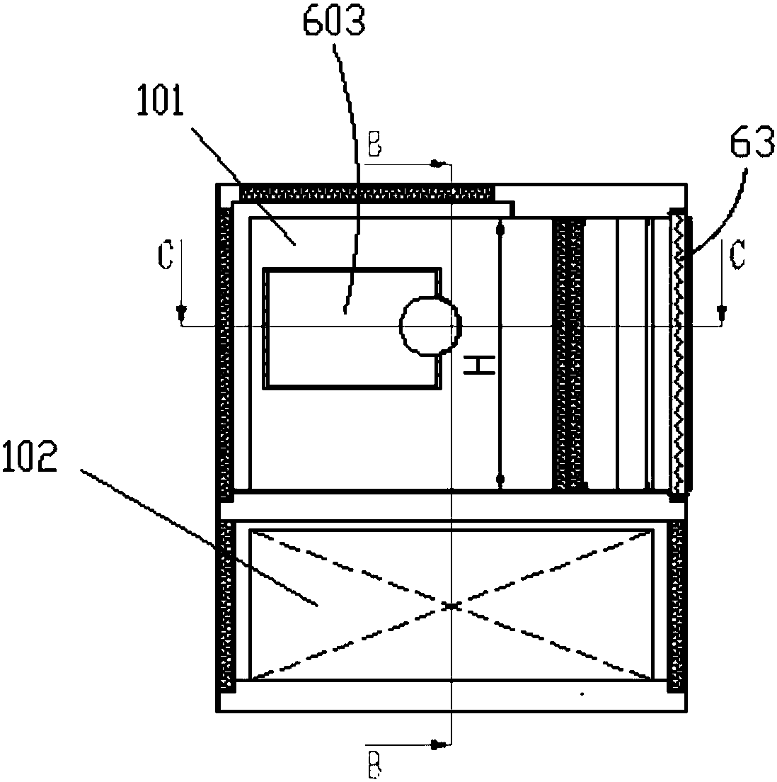
[0021] Such as Figure 1 to Figure 4 , the present invention discloses a high-speed centrifugal fan noise reduction cabinet, including a main cabinet 101, an electric control cabinet 102, an inlet filter 63 and a main machine 603, the main cabinet 101 and the electric control cabinet 102 are arranged in layers, and the main machine 603 is fixed on In the main cabinet 101, the inlet filter 63 is arranged on the outer wall of the main cabinet 101, and the outer wall of the main cabinet 101 is provided with an exhaust port 36, and also includes a small anechoic plate 601 and a large anechoic plate 602, and the large anechoic plate 602 is fixedly connected in the main cabinet 101, and the large sound-absorbing plate 602 and the inlet filter 63 are arranged parallel to each other, and a first gap is formed between the two ends of the large sound-absorbing plate 602 and the ...


PUM


Abstract

The invention discloses a silencing machine cabinet of a high-speed centrifugal-type fan. The silencing machine cabinet comprises a main machine cabinet body, an electric control cabinet body, an inlet filter and a main machine, the main machine cabinet body and the electric control cabinet body are arranged in a vertical layered mode, and the main machine is fixed into the main machine cabinet body. The inlet filter is arranged on the outer wall of the machine cabinet body, an exhaust port is formed in the outer wall of the main machine cabinet body, and the silencing machine cabinet furthercomprises small silencing plates and a large silencing plate, the large silencing plate is fixedly connected into the main machine cabinet body, and the large silencing plate and the inlet filter arearranged in parallel. First gaps are formed between the two ends of the large silencing plate and the inner wall of the main machine cabinet body, the two small silencing plates are arranged between the large silencing plate and the inlet filter, and a second gap is formed between the two small silencing plates. The silencing machine cabinet is simple in structure and good in silencing effect.

Description

Technical field: [0001] The invention relates to a muffler cabinet for a high-speed centrifugal fan. Background technique: [0002] Most of the high-speed centrifugal fans use magnetic bearings or air bearings and high-speed permanent magnet synchronous motor technology, which makes their energy-saving effect remarkable, and are widely used in medicine, environmental protection, chemical industry, petroleum and other industries. The cabinet structure of the fan is divided into two parts: the main cabinet and the electric control cabinet. The running speed of the main engine in the main cabinet is about 15000 rpm to 40000 rpm. Without noise control, it will cause troubles to the work of on-site workers and the lives of nearby residents, and in severe cases, it will affect people's physical and mental health. [0003] The shape of the existing fan cabinet is generally hexahedron, the inlet filter and the exhaust port are distributed in the main cabinet, the cabinet door is we...

Claims


Application Information

Patent Timeline
Patent Type & Authority Applications(China)
IPC IPC(8): F04D29/66F04D29/42F04D29/70
CPCF04D29/4226F04D29/663F04D29/664F04D29/703
Inventor 余知义孙益龙吴立华董继勇
Owner NANJING CIGU TECH CORP LTD
Learn More