
Dismounting device for main machine front cover and dismounting method for main machine front cover

A technology for dismantling devices and front covers, applied in metal processing, metal processing equipment, manufacturing tools, etc., can solve the problems of a large amount of labor, unsatisfactory, and reduced competitiveness, and achieve the goals of reducing damage rate, flexible movement, and reducing production costs Effect

Pending Publication Date: 2018-07-06
GUANGDONG JINHONGDA AUTOMATION TECH CO LTD
View PDF5 Cites 1 Cited by
  • Summary
  • Abstract
  • Description
  • Claims
  • Application Information

AI Technical Summary

Problems solved by technology

[0003] The host computer of the computer includes a front cover and a side cover, and the front cover and the side cover are pressed and connected to form an integrated structure with a storage space. There is a gap at the connection between the front cover and the side cover. It is necessary to remove the front cover of the main engine in order to assemble other parts in the main engine. In related technologies, removing the front cover is manual removal. This removal mode has low production efficiency and high production cost, which cannot meet the needs of the market.
[0004] The production method of manually removing the front cover in the related art requires a lot of labor, thereby greatly increasing the production cost and reducing the competitiveness of the enterprise

Method used


Image

  • Dismounting device for main machine front cover and dismounting method for main machine front cover
  • Dismounting device for main machine front cover and dismounting method for main machine front cover
  • Dismounting device for main machine front cover and dismounting method for main machine front cover

Examples


Embodiment Construction

[0033] The following will clearly and completely describe the technical solutions in the embodiments of the present invention. Obviously, the described embodiments are only some of the embodiments of the present invention, rather than all the embodiments. Based on the embodiments of the present invention, all other embodiments obtained by persons of ordinary skill in the art without making creative efforts belong to the protection scope of the present invention.

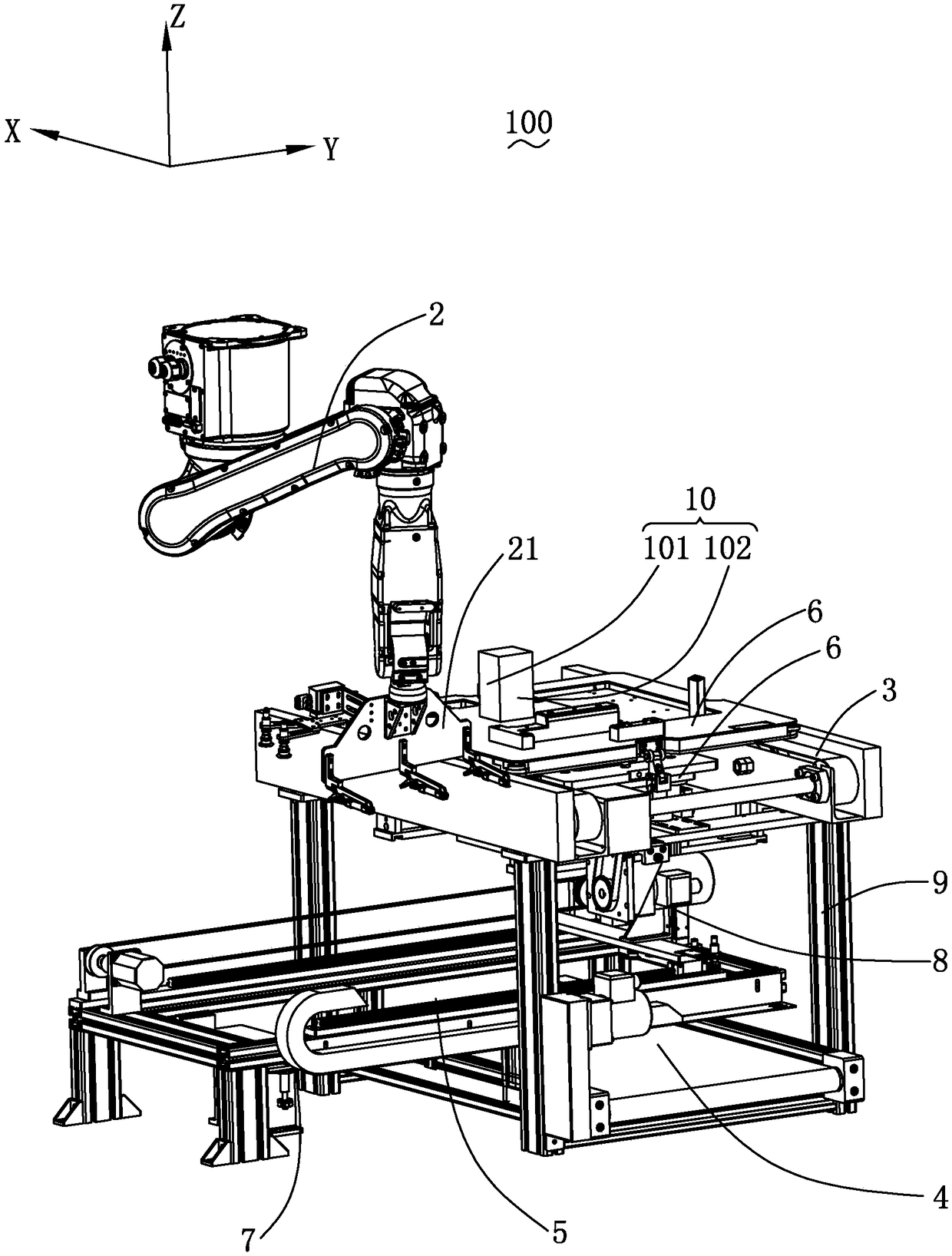
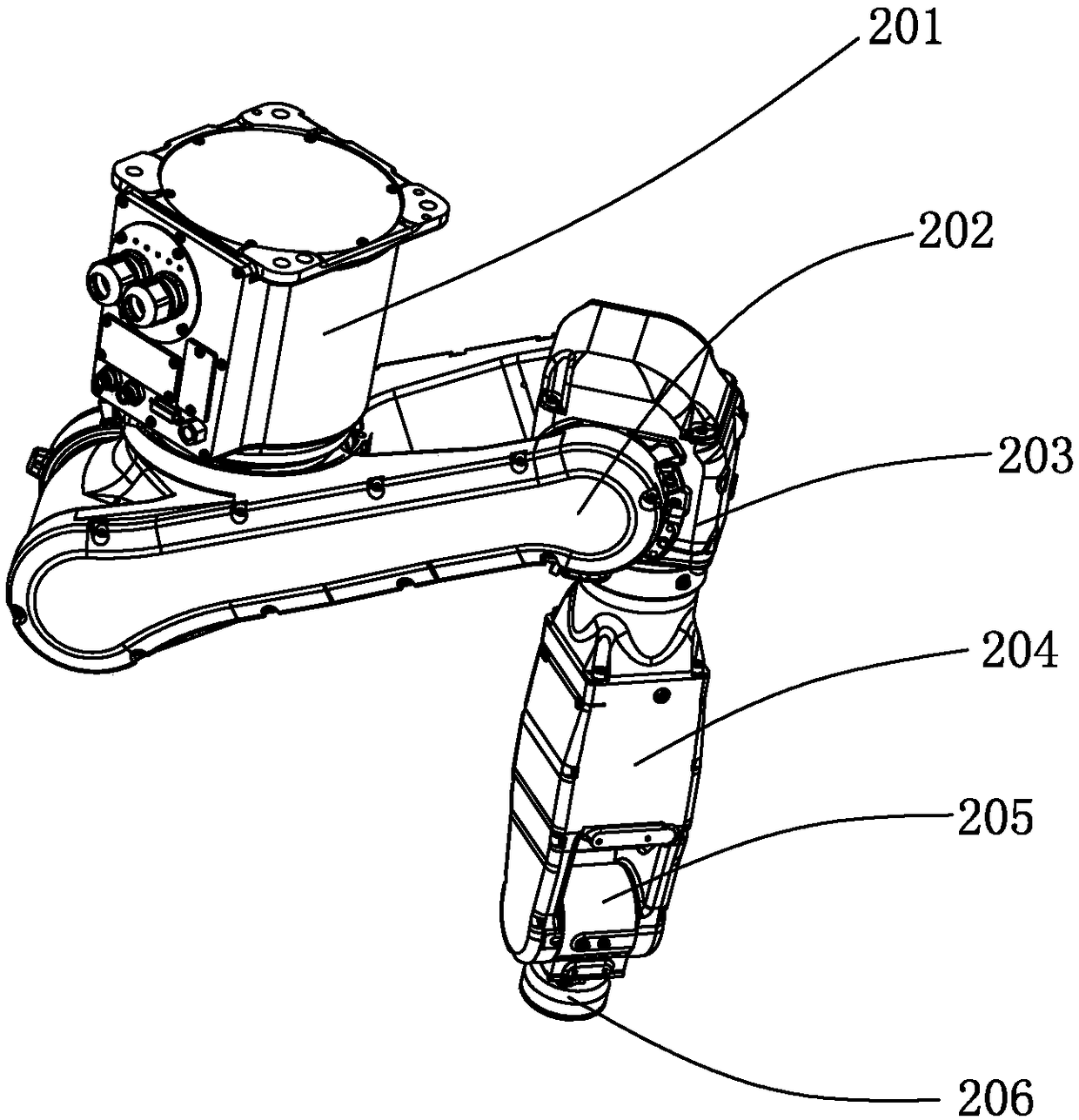
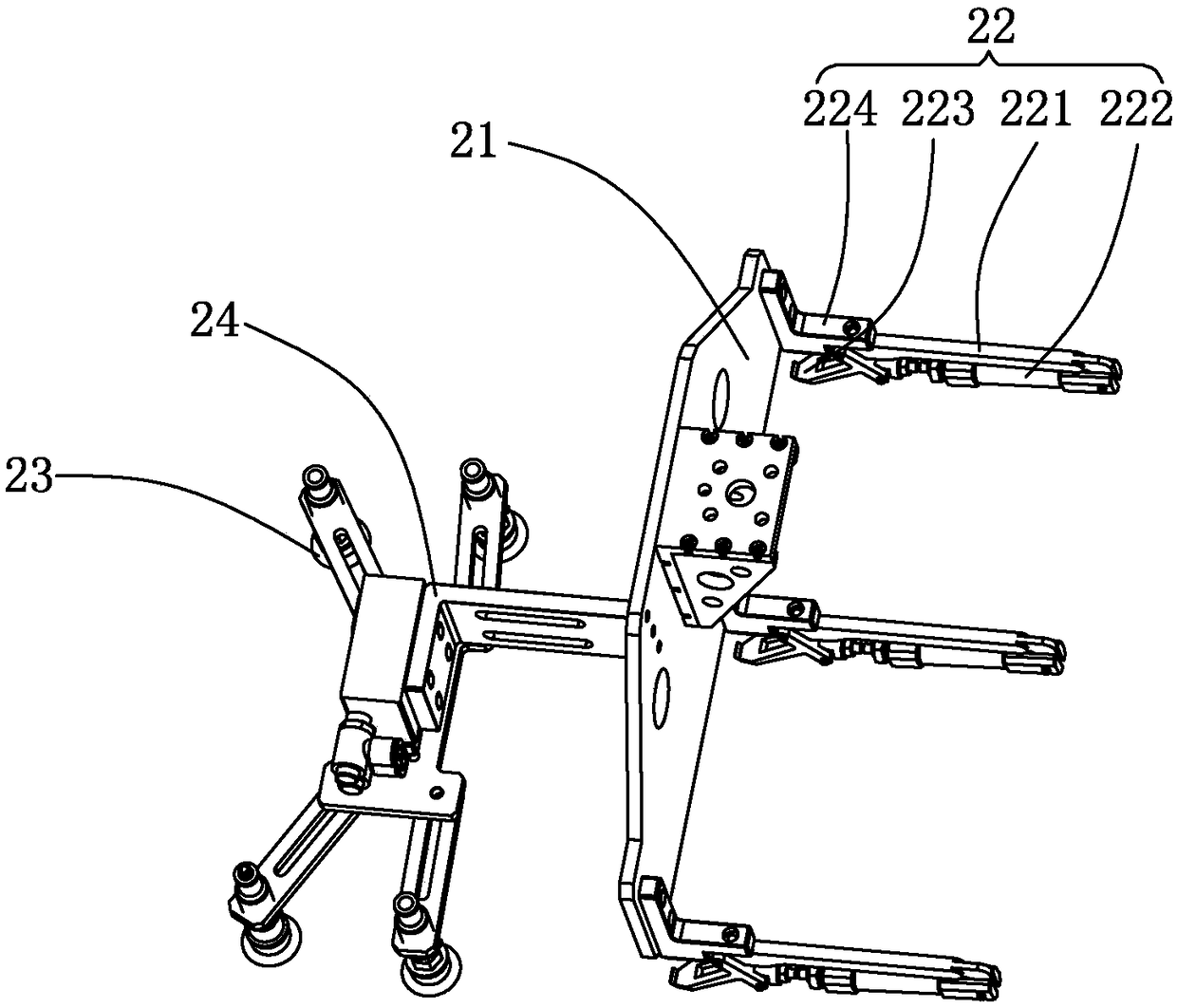
[0034] see figure 1 , is a schematic diagram of the structure of the device for removing the front cover of the main unit of the present invention. The present invention provides a host front cover removal device 100, which is used to remove a host 10 including a front cover 101 and a side cover 102 and a storage space (not numbered) enclosed by the front cover 101 and the side cover 102. The host front cover removal device 100 includes a processing board 1 for carrying the host 10, a six-axis manipulator 2 for remo...


PUM


Abstract

The invention discloses a dismounting device for a main machine front cover. The device comprises a machining board, a six-axis mechanical arm, a upper line body, a lower line body, two linear guide rails, a upper-layer jacking mechanism, a lower-layer jacking mechanism, a horizontal moving and a main body support, wherein the machining board is used for bearing the main machine, the six-axis mechanical arm used for disassembling the front cover of the main machine, wherein the upper line body is used for bearing the processing board and enabling the processing board to move along the conveying direction, and the lower line body is spaced from the upper line body and is used for bearing the front cover and enabling the front cover to move along the conveying direction, and the two linear guide rails are clamped between the upper line body and the lower line body, the upper-layer jacking mechanism is arranged between the upper-layer wire body and the linear guide rail and is used for fixing the machining plate above the upper-layer wire body, is arranged between the two linear guide rails and is used for receiving the lower-layer jacking mechanism of the front cover which is disassembled by the six-axis mechanical arm, horizontal moving and a main body support. The invention further provides a disassembling method for the main machine front cover. Compared with the related art,the device and method for disassembling the main machine front cover are more flexible in disassembly, low in damage rate and are capable of reducing the production cost.

Description

technical field [0001] The invention relates to the field of automatic mechanical devices, in particular to a mainframe front cover removal device and a mainframe front cover removal method for automatically disassembling a computer mainframe. Background technique [0002] As computer technology becomes more and more mature, the network coverage becomes wider and wider, and the demand for computers increases day by day. In order to supply the increasing demand for computers, the production efficiency of computers also needs to be further improved. [0003] The host computer of the computer includes a front cover and a side cover, and the front cover and the side cover are pressed and connected to form an integrated structure with a storage space. There is a gap at the connection between the front cover and the side cover. It is necessary to remove the front cover of the main engine in order to assemble other parts in the main engine. In the related art, removing the front co...

Claims


Application Information

Patent Timeline
IPC IPC(8): B23P19/04
CPCB23P19/04
Inventor 陈升明刘鹏陈梦思
Owner GUANGDONG JINHONGDA AUTOMATION TECH CO LTD
Learn More