
OLED display panel and display device

A display panel and substrate substrate technology, applied in the direction of electrical components, circuits, computer components, etc., can solve problems such as not being able to adapt to new user needs, and achieve the effect of reducing the incidental area

Active Publication Date: 2018-07-03
BOE TECH GRP CO LTD
View PDF4 Cites 61 Cited by
  • Summary
  • Abstract
  • Description
  • Claims
  • Application Information

AI Technical Summary

Problems solved by technology

The traditional OLED display panel with fingerprint recognition, camera, microphone, etc. on the whole surface can no longer meet the needs of new users

Method used


Image

  • OLED display panel and display device
  • OLED display panel and display device
  • OLED display panel and display device

Examples


Embodiment Construction

[0034] The specific implementation manners of the OLED display panel and the display device provided by the embodiments of the present invention will be described in detail below with reference to the accompanying drawings.

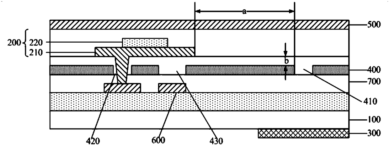
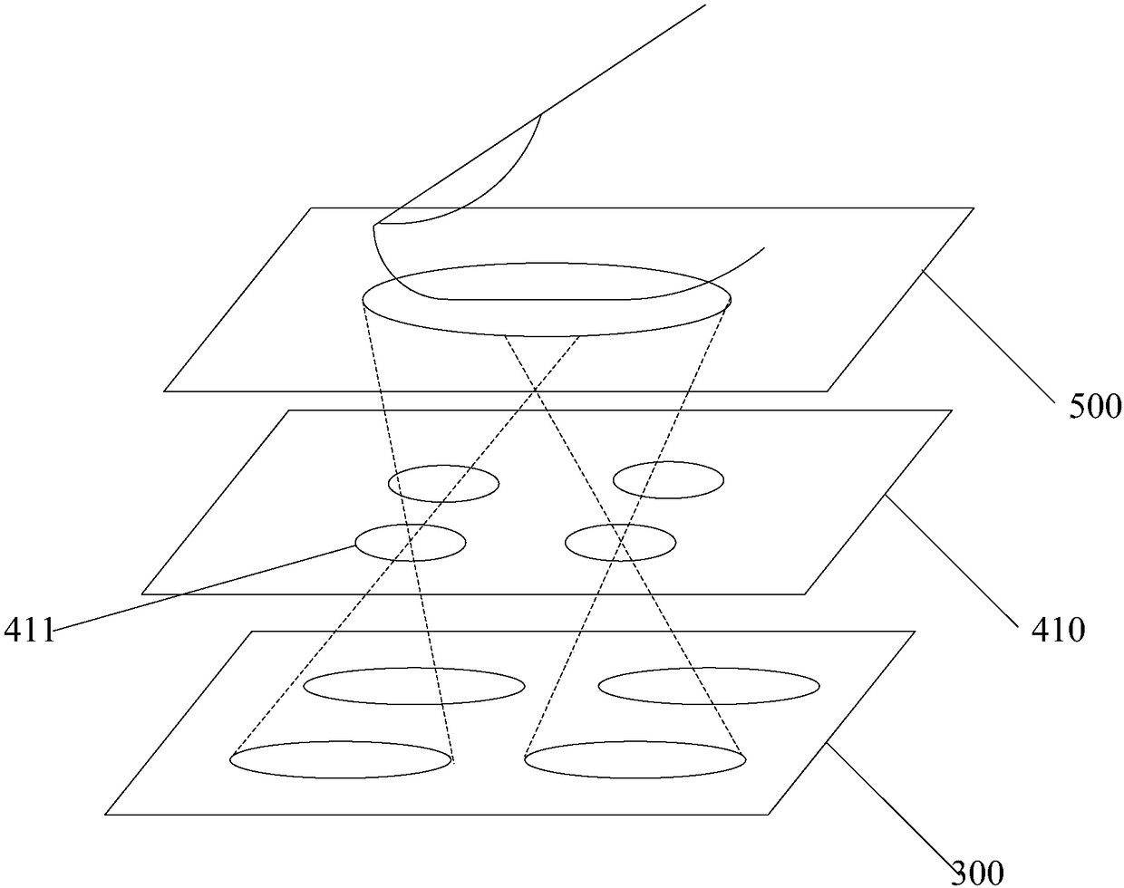
[0035] An embodiment of the present invention provides an OLED display panel, such as figure 1 As shown, it specifically includes: a base substrate 100, a plurality of OLED light emitting devices 200 disposed on one side of the base substrate 100, signal wiring and control devices correspondingly connected to each OLED light emitting device 200, disposed on the base substrate The image sensor 300 on the other side or the same side of 100, and the light-shielding layer 400 with at least one small hole imaging area 410 disposed between the image sensor 300 and the film layer where each OLED light-emitting device 200 is located; wherein,

[0036] Such as figure 2 As shown, the orthographic projection of the small hole imaging area 400 on the base substrate...


PUM


Abstract

The invention discloses an OLED display panel and a display device. An image sensor is arranged below OLED devices; and light shading layers, each of which has at least one small hole imaging region,are arranged between the image sensor and the OLED devices. With small hole imaging regions corresponding to gaps among all OLED devices and being staggered with shading components in signal routing units and control devices in the light shading layer, imaging of an object above the OLED display panel is carried out at the image sensor; for example, when a finger is placed above the OLED display panel corresponding to the small hole imaging region, fingerprint acquisition and recognition are realized. Therefore, the fingerprint recognition function is realized in the display area of the OLED display panel; and thus the attached area of the whole display device can be reduced and a frameless design can be realized.

Description

technical field [0001] The invention relates to the field of display technology, in particular to an OLED display panel and a display device. Background technique [0002] Currently, organic light-emitting diode (Organic Light-Emitting Diode, OLED) display panels are more and more developing towards narrow frame and full-surface display. The traditional OLED display panel with fingerprint recognition, camera, microphone, etc. on the whole surface can no longer meet the needs of new users. Therefore, it is imperative to develop a fingerprint identification technology in the display (AA) area of ​​the display panel, which can effectively reduce the incidental area of ​​the OLED display panel and further achieve full-surface display. Contents of the invention [0003] In view of this, an embodiment of the present invention provides an OLED display panel and a display device, which are used to implement a fingerprint recognition function in the display area of ​​the OLED disp...

Claims


Application Information

Patent Timeline
Patent Type & Authority Applications(China)
IPC IPC(8): H01L27/32
CPCH10K59/88H10K59/65G06V40/1335G06V40/1318H10K59/126H10K59/131H10K59/123
Inventor 孙艳六史世明刘政
Owner BOE TECH GRP CO LTD
Learn More