Novel water conservation device

A new type of water conservancy technology, applied in the direction of lighting devices, hoisting devices, lighting devices, etc., can solve the problems of troublesome disassembly and assembly of pulley well ropes, easy aging and fracture of well ropes, low degree of automation, etc., and achieve uniform well rope winding work , Improve the running stability and the winding speed of the well rope, and the effect of low maintenance cost

Inactive Publication Date: 2018-07-03
楼晓帅
View PDF0 Cites 0 Cited by
  • Summary
  • Abstract
  • Description
  • Claims
  • Application Information

AI Technical Summary

Problems solved by technology

In order to draw water safely and conveniently, a potter's wheel will be set up next to the well, but the potter's wheel needs to be rolled by hand to retract the well rope, which has a low degree of automation, and the well rope is easily distributed unevenly when it is wrapped around the head of the potter's wheel, which affects normal use. The well rope is blown by the wind. The rain is easy to age and break, so it needs to be replaced in time. The disassembly and assembly of the traditional potter's wheel well rope is very troublesome and dangerous

Method used


Image

  • Novel water conservation device
  • Novel water conservation device
  • Novel water conservation device

Examples


Embodiment Construction

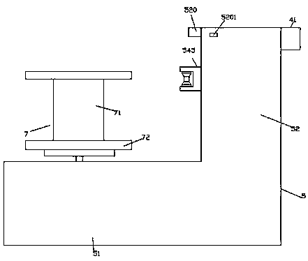
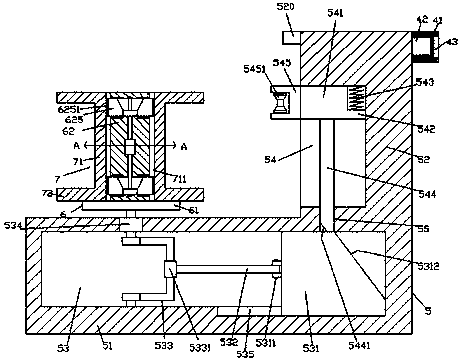
[0021] like Figure 1-Figure 5 Shown, a kind of novel water conservancy device of the present invention comprises the well rope winding frame 5 that is fixedly installed on the water well edge that is made up of first frame 51 and second frame 52, and in described first frame 51 There is a hollow cavity 53 extending left and right, the right side of the hollow cavity 53 is provided with a first sliding groove 535, and a sliding block 531 is provided in the first sliding groove 535, and the hollow A flexible connection part 5311 is provided on the left side of the sliding block 531 in the cavity 53, and a pushing rod 532 extending to the left is flexibly connected in the flexible connecting part 5311, and the left tail of the pushing rod 532 is provided with a A fixed sleeve 5331, the fixed sleeve 5331 is provided with a half-ring rod 533, the front side of the half-ring rod 533 is connected with the inner wall of the front side of the hollow cavity 53 in rotation, and the rear...


PUM


Abstract

The invention discloses a novel water conservation device. The novel water conservation device comprises a well rope winding rack which is composed of a first rack and a second rack and is fixedly mounted on the edge of a well, wherein a hollow cavity is arranged in the first rack in a left-right extending mode; a first slip slot is formed in the right side of the hollow cavity; a slip block is connected in the first slip slot in a slip fit mode; a flexible connecting part is arranged on the left side surface of the slip block in the hollow cavity; a pushing rod which extends towards the leftside is flexibly connected in the flexible connecting part; the tail part of the left side of the pushing rod is equipped with a fixed sleeve; a semi-ring rod part is arranged in the fixed sleeve; thefront side of the semi-ring rod part is rotatably connected with the inner wall of the front side of the hollow cavity in a matched mode; the rear side of the semi-ring rod part is connected with a well rope winding motor in a matched mode; the well rope winding motor is arranged in the inner wall of the rear side of the hollow cavity and is fixedly connected; a second slip slot which is formed in the front-rear extending mode is formed in the left side surface of the second rack; and a second slip block is arranged in the second slip slot. The novel water conservation device is simple in structure, can realize quick mounting and dismounting, increases replacing speed of a bobbin, and enables well rope winding work to be uniform.

Description

technical field [0001] The invention relates to the technical field of water conservancy equipment, in particular to a novel water conservancy device. Background technique [0002] In areas with abundant groundwater, people will dig wells to extract groundwater for irrigation or living. In order to draw water safely and conveniently, a potter's wheel will be set up next to the well, but the potter's wheel needs to be rolled by hand to retract the well rope, which has a low degree of automation, and the well rope is easily distributed unevenly when it is wrapped around the head of the potter's wheel, which affects normal use. The well rope is blown by the wind. It is easy to age and break due to rain, so it needs to be replaced in time. The disassembly and assembly of the traditional pulley well rope is very troublesome and dangerous. Contents of the invention [0003] The technical problem to be solved by the present invention is to provide a new water conservancy device,...

Claims


Application Information

Patent Timeline
Patent Type & Authority Applications(China)
IPC IPC(8): B66D1/12B66D1/28B66D1/30B66D1/38B66D1/54F21V33/00
CPCB66D1/12B66D1/28B66D1/30B66D1/38B66D1/54B66D2700/0141B66D2700/0183B66D2700/0191F21V33/00
Inventor 楼晓帅杨丽君
Owner 楼晓帅
Why Eureka
Try Eureka