Improved electric power supply safe transmission device

A safe transmission and improved technology, applied in the field of improved power supply safety transmission devices, can solve problems such as electric shock accidents, influence of electrical equipment, power failure of electrical equipment, etc., to achieve high electrical safety and reduce potential safety hazards. , the effect of power off stability

Inactive Publication Date: 2018-06-29
吴美俊
View PDF0 Cites 2 Cited by
  • Summary
  • Abstract
  • Description
  • Claims
  • Application Information

AI Technical Summary

Problems solved by technology

[0002] The news of electric shock accidents occurs from time to time, and the number of people who die from electric shock accidents every year is very large. Among them, the people who are prone to electric shock are generally the staff who are often exposed to electricity and some people who lack safety awareness. For the use of electrical equipment, we will install many power sockets on the wall. When using, insert the conductive head into the power socket to complete the power supply of the electrical equipment. As we all know, the conductive sheet is almost leaked in the slot, and the slot It is connected to the outside world. Due to the curiosity of young children, they will insert the metal rod into the slot, and the metal rod will contact the conductive sheet, which will lead to electric shock accidents, and in severe cases, it will cause casualties to young children. , so the traditional power base has great safety hazards, and when the traditional power base cooperates with the conductive rod, it only relies on the elastic clamping of the input conductive sheet to maintain the power-on state of the electrical equipment, but this state is not stable enough. When someone accidentally touches the power connector or the wire, it will cause the power connector to loosen or fall off. Therefore, it will cause accidental power failure of the electrical equipment, which will easily affect the electrical equipment.

Method used


Image

  • Improved electric power supply safe transmission device
  • Improved electric power supply safe transmission device
  • Improved electric power supply safe transmission device

Examples


Embodiment Construction

[0025] All features disclosed in this specification, or steps in all methods or processes disclosed, may be combined in any manner, except for mutually exclusive features and / or steps.

[0026] Any feature disclosed in this specification (including any appended claims, abstract and drawings), unless expressly stated otherwise, may be replaced by alternative features which are equivalent or serve a similar purpose. That is, unless expressly stated otherwise, each feature is one example only of a series of equivalent or similar features.

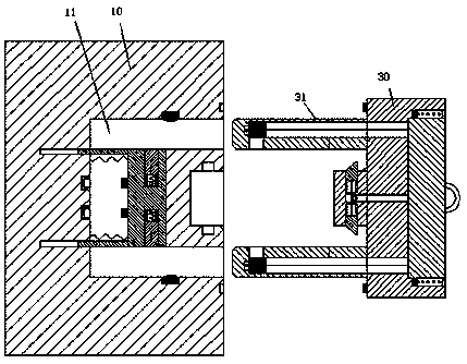
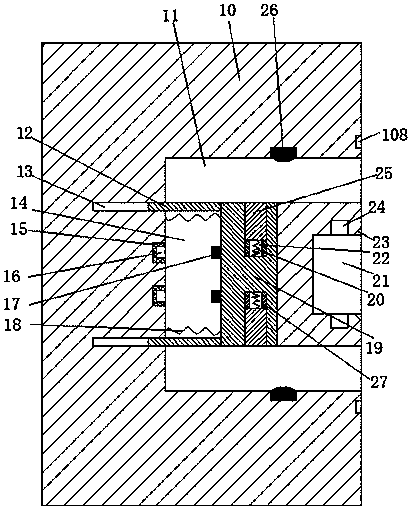
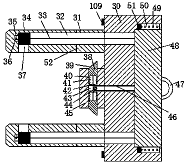
[0027] like Figure 1 to Figure 6 As shown, an improved electric power safety transmission device of the device of the present invention includes a power base 10 fixedly installed in the wall and a conductive head matched with the power base 10, and the power base 10 is symmetrically arranged up and down. Slots 11, the power base 10 is located between the two slots 11 and is provided with a sliding chamber 14 communicating with the two slots ...


PUM


Abstract

The invention discloses an improved electric power supply safe transmission device. The improved electric power supply safe transmission device comprises a power supply socket fixedly installed in a wall body and an electric conduction head matched with the power supply socket, slots are symmetrically arranged up and down in the power supply socket, a sliding cavity communicating the two slots isarranged between the two slots in the power supply socket, a sliding body is installed in the sliding cavity by means of sliding left and right, first sliding grooves orthogonal to the slots are symmetrically arranged up and down in the sliding body, openings of the first sliding grooves face the slots, a sliding iron block is installed in the first sliding groove in a sliding way, power supply blocks connected with the mains supply are symmetrically arranged up and down in the wall at the left end of the sliding cavity, a power supply port is arranged in the power supply block, an opening ofthe power supply port faces the sliding cavity, electric conduction blocks matched with the power supply port are symmetrically installed up and down in the left end face of the sliding body, and an elastic transmission electric conduction head is fixed on the end face, far from the sliding cavity, of the slot.

Description

technical field [0001] The invention relates to the field of electricity use by electric equipment, in particular to an improved power supply safety transmission device. Background technique [0002] The news of electric shock accidents occurs from time to time, and the number of people who die from electric shock accidents every year is very large. Among them, the people who are prone to electric shock are generally the staff who are often exposed to electricity and some people who lack safety awareness. For the use of electrical equipment, we will install many power sockets on the wall. When using, insert the conductive head into the power socket to complete the power supply of the electrical equipment. As we all know, the conductive sheet is almost leaked in the slot, and the slot It is connected to the outside world. Due to the curiosity of young children, they will insert the metal rod into the slot, and the metal rod will contact the conductive sheet, which will lead t...

Claims


Application Information

Patent Timeline
IPC IPC(8): H01R13/447H01R13/62H01R13/627
CPCH01R13/447H01R13/6205H01R13/6278
Inventor 吴美俊
Owner 吴美俊
Why Eureka
Try Eureka