
Synchronous RMU (ring main unit) switch provided with three permanent magnets

A technology of permanent magnet synchronization and ring network cabinets, which is applied in the field of ring network cabinets, can solve the problems of closing phase loss, affecting power safety, and opening phase loss, so as to ensure safe operation and prevent closing phase loss or separation Gate phase loss, the effect of ensuring synchronization

Pending Publication Date: 2018-06-29
JIANGSU YAKAI ELECTRIC
View PDF0 Cites 0 Cited by
  • Summary
  • Abstract
  • Description
  • Claims
  • Application Information

AI Technical Summary

Problems solved by technology

The switch of the ring main unit in the prior art is controlled by a single permanent magnet mechanism for opening and closing. The disadvantage is that in extreme cases, such as the lack of energy of the driving power supply of the permanent magnet mechanism, it will cause a phase loss in closing. , open phase loss; directly affect the safety of electricity

Method used


Image

  • Synchronous RMU (ring main unit) switch provided with three permanent magnets
  • Synchronous RMU (ring main unit) switch provided with three permanent magnets
  • Synchronous RMU (ring main unit) switch provided with three permanent magnets

Examples


Embodiment Construction

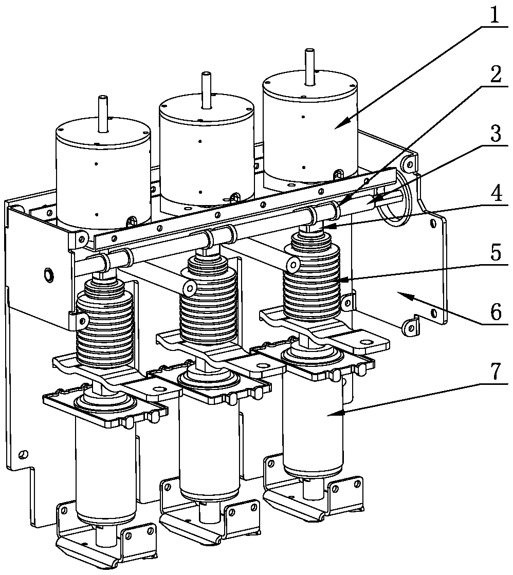
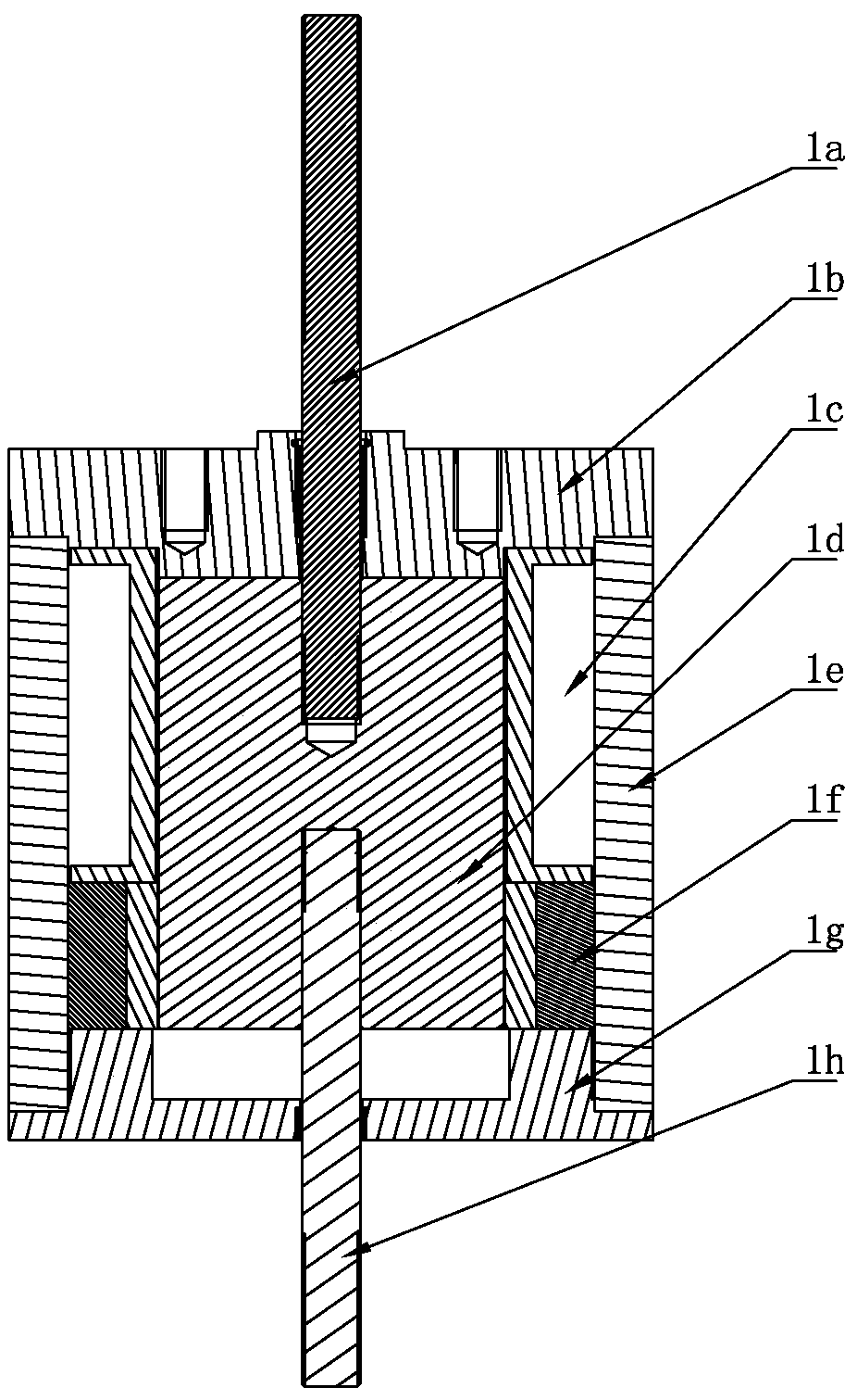
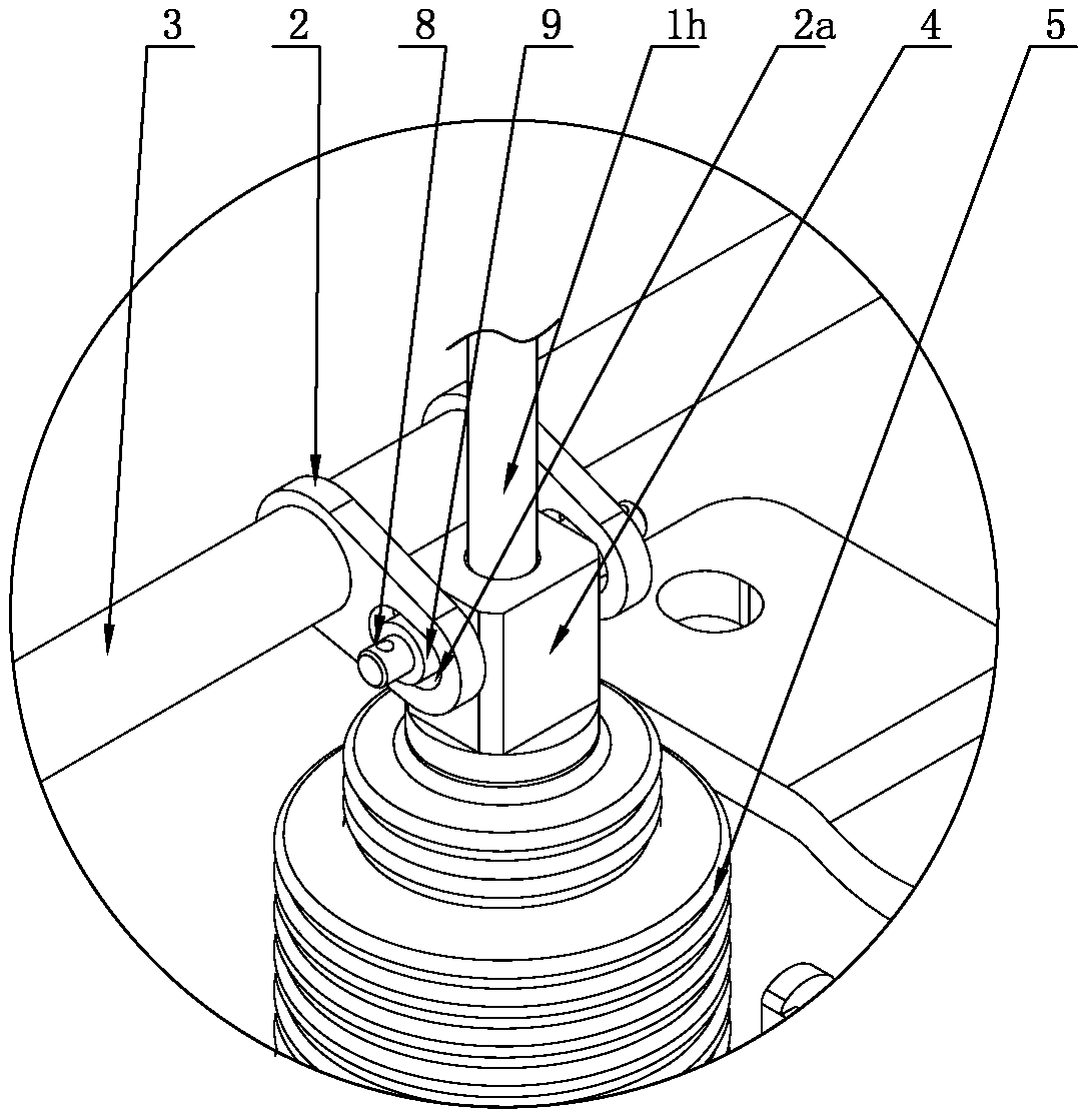
[0016] Such as Figure 1-3 A three-permanent-magnet synchronous ring network cabinet switch as shown includes a cabinet body 6, and a solid-sealed pole and a permanent magnet mechanism 1 are arranged in the cabinet body 6, and a vacuum interrupter 7 is arranged in the solid-sealed pole. Mechanism 1 includes a transmission rod that drives the moving conductive rod in the vacuum interrupter 7 to open and close. The transmission rod is connected to the movable conductive rod in the vacuum interrupter 7 through the insulating rod 4, and the insulating rod 4 is connected to the synchronous shaft 3 through the connecting plate 2. connected, the two ends of the synchronous shaft 3 are installed on the cabinet body 6, one end of the connecting plate 2 is fixedly set on the synchronous shaft 3, and the other end of the connecting plate 2 is hinged on the insulating rod 4, so that the insulating rod 4 drives when it moves up and down. The synchronous shaft 3 rotates, the upper end of th...


PUM


Abstract

The invention discloses a synchronous RMU (ring main unit) switch provided with three permanent magnets. The synchronous RMU switch comprises a cabinet body, wherein solid-sealed polar poles and permanent magnet mechanisms are arranged in the cabinet body; vacuum arc-extinguishing chambers are arranged in the solid-sealed polar poles; each permanent magnet mechanism comprises a drive rod for driving opening and closing of a dynamic conductive rod in the corresponding vacuum arc-extinguishing chamber, the drive rod is connected with the dynamic conductive rod in the vacuum arc-extinguishing chamber through an insulating pull rod, the insulating pull rod is connected with a synchronizing shaft through a connecting plate, two ends of the synchronizing shaft are mounted on the cabinet body, one end of the connecting plate is fixedly mounted on the synchronizing shaft in a sleeving manner, and the other end of the connecting plate is hinged on the insulating pull rod, so that the insulatingpull rod drives the synchronizing shaft to rotate during vertical moving. According to the synchronous RMU switch, the synchronizing shaft is connected with the three permanent magnet mechanisms, synchronism of the permanent magnet mechanisms is guaranteed during fast acting in the aspect of principle, closing phase loss or opening phase loss is fundamentally eradicated under the condition of fast opening is guaranteed, therefore, safe operation of a grid is guaranteed, and the synchronous RMU switch can be applied to a RMU.

Description

technical field [0001] The invention relates to a ring network cabinet, in particular to a ring network cabinet switch. Background technique [0002] With the development of the domestic economy, the demand for the capacity of the ring network power supply system continues to increase, and the number of ring network cabinets used in the power grid is also increasing. This mainly depends on the outstanding advantages of the ring network cabinet, which has a simple and compact structure, Small size, flexible operation, reliable interlocking, convenient expansion of cabinet type, etc., suitable for switching stations, box-type substations, residential quarters, industrial and mining enterprises, large shopping malls, airports, subways, railways, chemicals and other places. The switch of the ring main unit in the prior art is controlled by a single permanent magnet mechanism for opening and closing. The disadvantage is that in extreme cases, such as the lack of energy of the dri...

Claims


Application Information

Patent Timeline
Patent Type & Authority Applications(China)
IPC IPC(8): H01H33/666H01H9/00
CPCH01H9/0072H01H33/666
Inventor 吴学海金炼秦朝阳唐福礼
Owner JIANGSU YAKAI ELECTRIC
Learn More