
Calibration method of automatic optical detection device, and automatic repairing system

An automatic optical detection and calibration method technology, which is applied in the direction of optical testing flaws/defects, etc., can solve problems such as unguaranteed, low calibration accuracy, and inability to be absolutely guaranteed

Active Publication Date: 2018-06-29
BOE TECH GRP CO LTD +1
View PDF7 Cites 5 Cited by
  • Summary
  • Abstract
  • Description
  • Claims
  • Application Information

AI Technical Summary

Problems solved by technology

However, this method cannot guarantee that during the two adjacent lens position confirmations, when a certain lens of AOI has a large offset, the Auto Repair (automatic repair equipment) lens cannot see the defect without repairing it, which reduces the product yield.
That is, this method cannot absolutely guarantee that the defects detected by each lens of AOI can be seen in the Auto Repair lens, the calibration accuracy is low, and the AOI lens needs to be repeatedly adjusted, and the calibration confirmation time is long

Method used


Image

  • Calibration method of automatic optical detection device, and automatic repairing system
  • Calibration method of automatic optical detection device, and automatic repairing system
  • Calibration method of automatic optical detection device, and automatic repairing system

Examples


Embodiment Construction

[0049] Reference will now be made in detail to the exemplary embodiments, examples of which are illustrated in the accompanying drawings. When the following description refers to the accompanying drawings, the same numerals in different drawings refer to the same or similar elements unless otherwise indicated. The implementations described in the following exemplary examples do not represent all implementations consistent with the present invention. Rather, they are merely examples of apparatuses and methods consistent with aspects of the invention as recited in the appended claims.

[0050] Before introducing the calibration method of the automatic optical inspection equipment and the automatic repair system in the embodiment of the present invention, the automatic repair system in the related art is briefly introduced.

[0051] In the related art, the automatic repair system includes automatic optical inspection equipment (AOI) and repair equipment (repair). Taking the repai...


PUM


Abstract

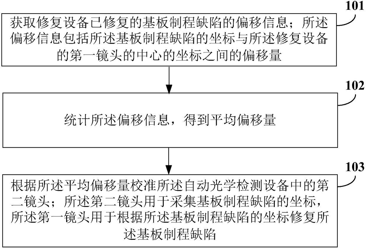
The invention relates to a calibration method of an automatic optical detection device, and an automatic repairing system. The calibration method of the automatic optical detection device comprises the following steps: acquiring offset information of a substrate process defect repaired by a repairing device, wherein the offset information includes an offset between the coordinates of the substrateprocess defect and the coordinates of the center of the first lens of the repairing device; carrying out statistical treatment on the offset information to obtain an average offset; and calibrating asecond lens in the automatic optical detection device according to the average offset, wherein the second lens is used for collecting the coordinates of the substrate process defect, and the first lens is used for repairing the substrate process defect according to the coordinates of the substrate process defect. In the embodiment of the invention, the calibration precision is improved, and the calibration confirmation time is shortened.

Description

technical field [0001] The invention relates to the field of display technology, in particular to a calibration method and an automatic repair system for automatic optical detection equipment. Background technique [0002] With the promotion and popularization of large-size TFT-LCD (Thin Film Transistor-Liquid Crystal Display, Thin Film Transistor-Liquid Crystal Display), Glass motherboards (substrates) are gradually increasing. In order to detect defects in various processes more accurately, automatic optical inspection equipment AOI (Automatic Optic Inspection, automatic optical inspection) usually uses multiple lenses to inspect the Glass motherboard in different areas. Since the defect information output by AOI is detected by multiple lenses, there are position errors in the installation and debugging of different lenses, resulting in differences between the output defect coordinates of each lens and the standard coordinate values. In order to ensure that the repair equi...

Claims


Application Information

Patent Timeline
IPC IPC(8): G01N21/95
CPCG01N21/95
Inventor 李鹏李坚李志宾赵宝杰郑云蛟崔家宾
Owner BOE TECH GRP CO LTD
Learn More