
Star sensor installation layout method based on staring attitude of remote sensing satellite

A technology for star sensors and remote sensing satellites, applied in the field of remote sensing satellites, can solve problems such as the complexity of star sensor layout methods, and achieve the effect of simple layout methods

Active Publication Date: 2020-07-31
CHANGGUANG SATELLITE TECH CO LTD
View PDF5 Cites 0 Cited by
  • Summary
  • Abstract
  • Description
  • Claims
  • Application Information

AI Technical Summary

Problems solved by technology

[0005] The present invention solves the disadvantages that the existing star-sensitive layout method is complicated, needs repeated iterations and can only satisfy the shortcomings of the limited attitude of the satellite
Then solve the problem of the effectiveness of the star sensitivity under the staring attitude of the satellite at one time

Method used


Image

  • Star sensor installation layout method based on staring attitude of remote sensing satellite
  • Star sensor installation layout method based on staring attitude of remote sensing satellite
  • Star sensor installation layout method based on staring attitude of remote sensing satellite

Examples


specific Embodiment approach 1

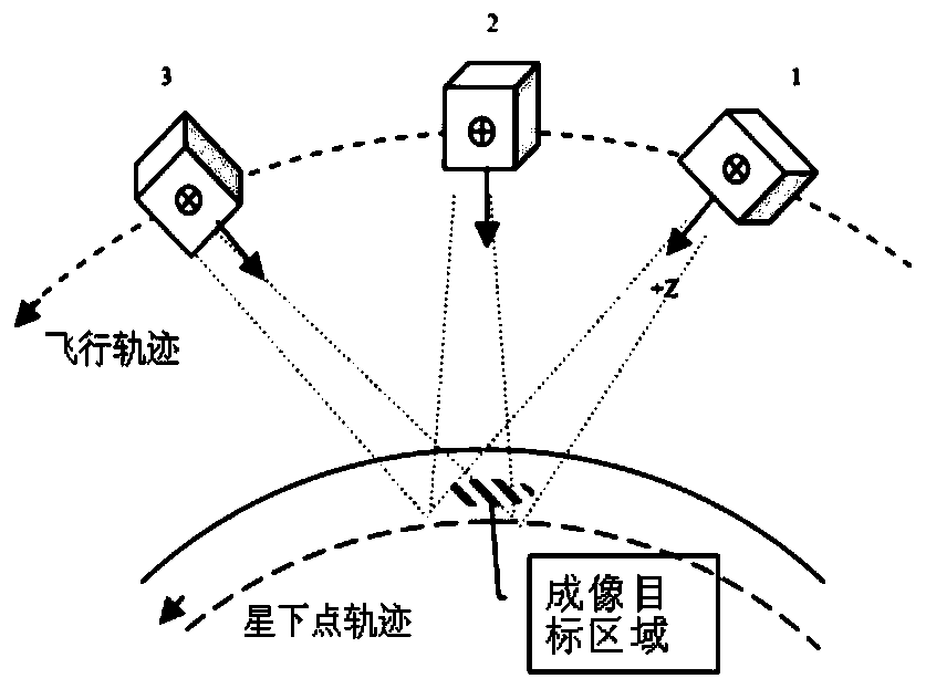
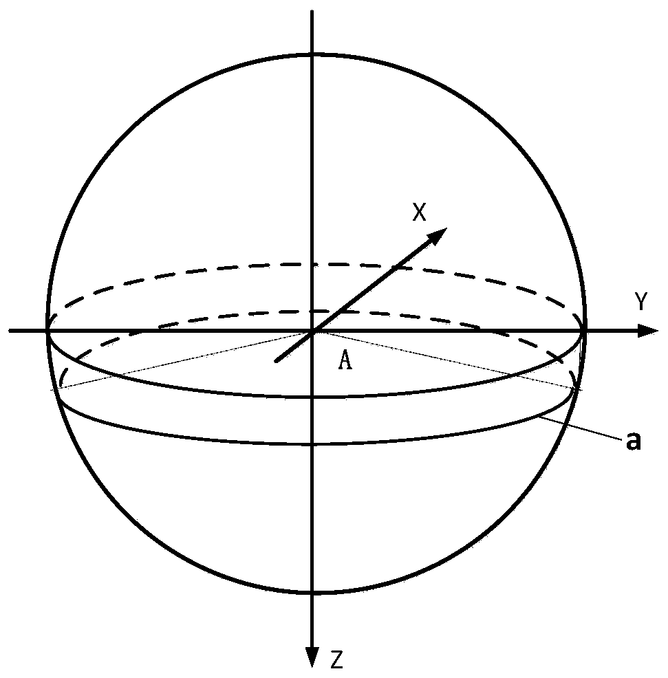
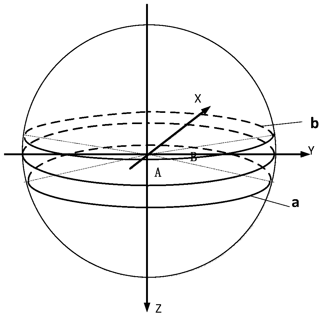
[0033] Specific implementation mode 1. Combination Figure 2 to Figure 7 Describe this embodiment, the star sensor installation layout method based on remote sensing satellite staring attitude, this method is realized by the following steps:

[0034] First, define two coordinate systems: the satellite orbit coordinate system and the satellite body coordinate system:

[0035] Satellite body coordinate system: the satellite body coordinate system refers to the rectangular coordinate system fixed to the satellite, the coordinate origin is at the center of mass of the satellite, and the +Z axis is perpendicular to the docking surface of the satellite docking ring and the transition section of the vehicle, pointing to the optical camera; +X The axis is in the docking plane between the satellite docking ring and the transition section of the vehicle, and is in the same direction as the satellite flight direction; the +Y axis is determined according to the right-hand rule.

[0036] ...

specific Embodiment approach 2

[0053] Specific embodiment two, combine Figure 8 and Figure 9 Describe this embodiment, this embodiment is the embodiment of the star sensor installation layout method based on remote sensing satellite staring attitude described in specific embodiment one:

[0054] In this embodiment, the altitude of the satellite orbit is set: 500.0km; the local time of the descending node: 11:30am; the sun avoidance angle of the star sensor: 25°; the earth avoidance angle of the star sensor: 25°; the staring angle of the satellite: 30°.

[0055] The included angle ∠A=70.3635° is calculated by the formula, and the range of the included angle between the sun vector and the orbital surface within a year is 3.5°~12.6° through orbital analysis software simulation analysis.

[0056] Using the method described in Embodiment 1, the calculated results are as follows Figure 9 shown. The area shown in the figure is the area that satisfies the Earth avoidance angle of the star sensor, and the dark...

specific Embodiment approach 3

[0060] Specific implementation mode three, combination Figure 10 and Figure 11 Describe this embodiment, this embodiment is the embodiment of the star sensor installation layout method based on remote sensing satellite staring attitude described in specific embodiment one:

[0061] Satellite orbit altitude: 636.0km; descending node local time: 10:00am; star sensor sun avoidance angle: 30°; star sensor earth avoidance angle: 30°; satellite gaze angle: 35°.

[0062] The included angle ∠A=67.4554° is calculated by the formula, and the range of the included angle between the sun vector and the orbital surface within a year is 23.5°~34.5° through orbital analysis software simulation analysis.

[0063] According to the method described in specific embodiment one, the calculated result is as follows Figure 11 shown. The area shown in the figure is the area that satisfies the Earth avoidance angle of the star sensor, and the dark area in the figure is the effective area where th...


PUM


Abstract

The invention relates to a star sensor installation and layout method based on a remote sensing satellite gaze gesture, and relates to the field of application to a remote sensing satellite on a sun-synchronous orbit. The problems that the existing star sensor layout method is complicated, the repeated iteration is used; in addition, the effectiveness at the limited gesture of the satellite can only be met are solved. A space spherical surface is built; a region for effectively avoiding stray light on the built space spherical surface is determined; a region for effectively avoiding sun lighton the space spherical surface is determined; the determined region for effectively avoiding the stray light and the region for effectively avoiding the sun light are subjected to intersection taking;the obtained intersection region is an effective region for star sensor effectiveness in the satellite gaze gesture; the sphere center of the space spherical surface is used as a starting point of the star sensor optical axis vector; a random spare point in the effective region is selected to be used as a terminal point of the star sensor optical axis vector; the installation layout position of the star sensor is determined. The star sensor layout method is simple, convenient and fast. The requirement for meeting the star sensor effectiveness under all gesture conditions can be directly solved in one step.

Description

technical field [0001] The invention relates to the field of remote sensing satellites applied to sun-synchronous orbits, and in particular to a star sensor installation and layout method based on staring imaging of remote sensing satellites, which is used to ensure the effectiveness of star sensors in the case of staring imaging of satellites. Background technique [0002] As a key attitude-sensitive component on a satellite, the star sensor's in-orbit validity is crucial to determine the satellite's attitude. As an optical sensor, the star sensor is particularly sensitive to sunlight and atmospheric light. In order to ensure the effectiveness of the star sensor, the angle between the optical axis of the star sensor and the sunlight (that is, the sun vector) should be greater than or equal to the solar avoidance angle of the star sensor. , the angle between the star sensor and the edge of the earth's atmosphere should be greater than or equal to the earth avoidance angle of...

Claims


Application Information

Patent Timeline
Patent Type & Authority Patents(China)
IPC IPC(8): G01C21/02G06F30/20
CPCG01C21/02G06F30/20
Inventor 陈志刚戴路徐开李峰刘萌萌童鑫范林东王国刚
Owner CHANGGUANG SATELLITE TECH CO LTD
Learn More