
Grate type damper and design method

A design method and damper technology, applied in protective buildings/shelters, building components, earthquake-proof and other directions, can solve the problems of high yield force adjustment cost, large yield displacement, late yielding of dampers, etc., and achieve yield force adjustment. low cost effect

Pending Publication Date: 2018-06-29
INST OF DISASTER PREVENTION +1
View PDF0 Cites 4 Cited by
  • Summary
  • Abstract
  • Description
  • Claims
  • Application Information

AI Technical Summary

Problems solved by technology

[0003] The object of the present invention is to propose a grate damper and its design method in order to solve the shortcomings of the existing damper such as late yield, large yield displacement and high yield force adjustment cost

Method used


Image

  • Grate type damper and design method
  • Grate type damper and design method
  • Grate type damper and design method

Examples


specific Embodiment approach 1

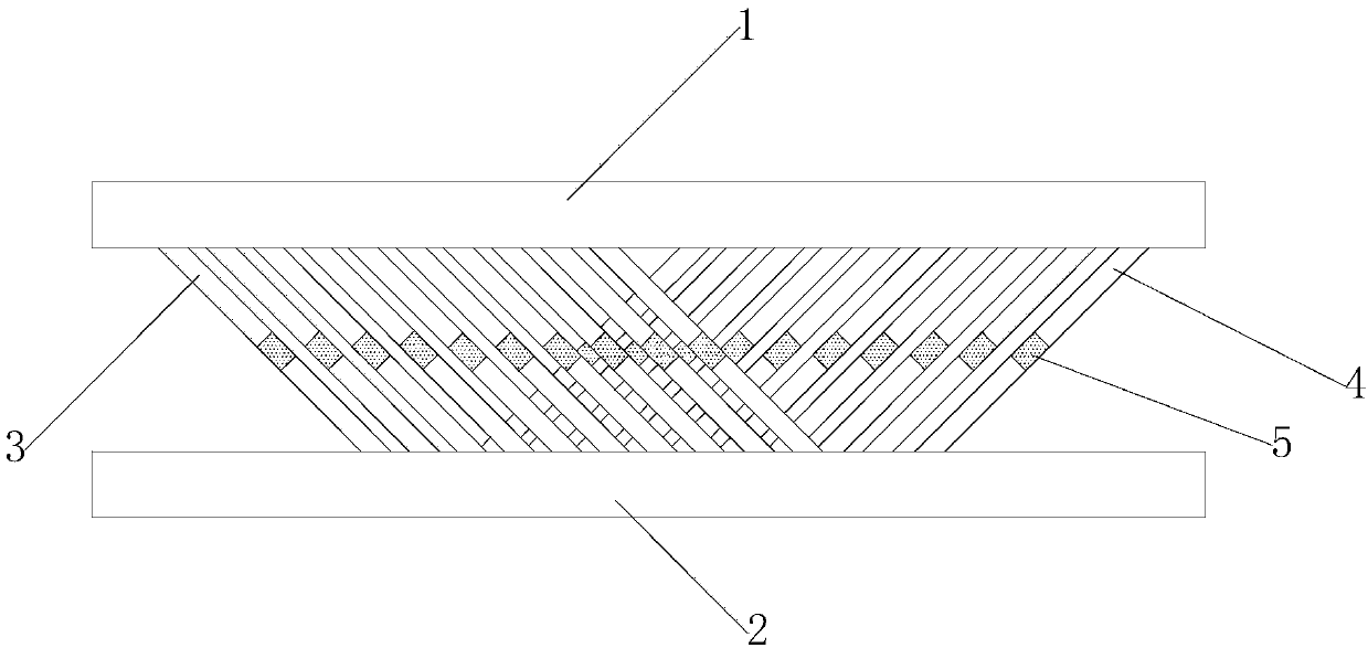
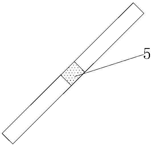
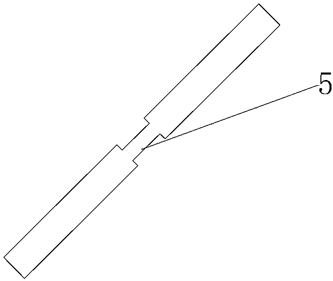
[0040] Specific implementation mode one: as figure 1 — image 3 As shown, a grate damper includes: an upper plate 1, a bottom plate 2, and a group of damper pressing racks 3 and a group of damper pulling racks 4 vertically intersecting;

[0041] The upper plate 1 and the bottom plate 2 are arranged in parallel, and a group of damper pressing racks 3 and a group of damper pulling racks 4 are arranged between the upper plate 1 and the bottom plate 2;

[0042] The lower surface of the upper plate 1 is provided with the upper groove of the damper pressing rack 3 and the upper groove of the damper pulling rack 4 in parallel, and the upper surface of the bottom plate 2 is respectively arranged with the upper groove of the damper pressing rack 3 and the damper pulling rack 4 The upper groove corresponds to the lower groove of the damper pressing rack 3 and the lower groove of the damper pulling rack 4;

[0043] A group of damper pressing racks 3 are arranged in parallel, one end of...

specific Embodiment approach 2

[0046] Embodiment 2: The difference between this embodiment and Embodiment 1 is that the necking section 5 is formed by the depressions provided on the front and rear end surfaces of each damper pressing rack 3 and damper pulling rack 4; Or the necking section 5 is composed of depressions provided on the left and right end surfaces of each damper pressing rack 3 and damper pulling rack 4 .

[0047] Other steps and parameters are the same as those in Embodiment 1.

specific Embodiment approach 3

[0048] Embodiment 3: The difference between this embodiment and Embodiment 1 or 2 is that the depression is a groove in the width direction of the press rack or pull rack through the damper, or the depression is a press rack through the damper Or pull the groove in the thickness direction of the rack.

[0049] Other steps and parameters are the same as those in Embodiment 1 or Embodiment 2.


PUM


Abstract

The invention relates to a grate type damper and a design method. According to the grate type damper and the design method, the problems that an existing damper is low in yield speed, large in yield displacement and high in yield force adjustment cost are solved. The grate type damper comprises an upper plate, a base plate, a group of damper pressure racks and a group of damper pulling racks, wherein the damper pressure racks and the damper pulling racks are vertically crossed; the upper plate and the base plate are arranged in parallel, and the damper pressure racks and the damper pulling racks which are vertically crossed are arranged between the upper plate and the base plate; the damper pressure racks are arranged in parallel, one ends of the damper pressure racks are arranged in upperdamper pressure rack grooves, the other ends of the damper pressure racks are arranged in lower damper pressure rack grooves, and acute angles formed by the damper pressure racks and the base plate are 45-degree angles; the damper pulling racks are arranged in parallel, and acute angles formed by the damper pulling racks and the base plate are 45-degree angles; and necking-down sections are arranged in the middles of each damper pressure rack and each damper pulling rack. The grate type damper is applied to the field of building aseismicity.

Description

technical field [0001] The invention relates to the field of anti-seismic buildings, in particular to a grate damper and a design method. Background technique [0002] With the improvement of the economic level, people require that after the housing construction experiences the earthquake, it can neither cause loss of life due to collapse, nor cause serious damage so as to cause heavy property loss. The latest anti-seismic theory points out that by installing advanced devices to increase the damping of building structures (a parameter that characterizes how much seismic energy is consumed) can effectively improve the anti-seismic capacity of building structures in order to achieve the goal of protecting life and property. However, the existing dampers have poor mechanical parameters and low efficiency, and it is urgent to develop a damper with limited cost but better parameters. Contents of the invention [0003] The object of the present invention is to propose a grate d...

Claims


Application Information

Patent Timeline
Patent Type & Authority Applications(China)
IPC IPC(8): E04B1/98E04H9/02
CPCE04H9/021
Inventor 郭迅何雄科
Owner INST OF DISASTER PREVENTION
Learn More