
Square tube beam-column joint and construction method thereof

A technology of tube-beam-column and joints, which is applied in the field of square tube-beam-column joints and its construction, and can solve problems such as low construction efficiency, poor stability, and impact on building safety

Inactive Publication Date: 2018-06-29
新昌县丽晶工业产品设计有限公司
View PDF0 Cites 4 Cited by
  • Summary
  • Abstract
  • Description
  • Claims
  • Application Information

AI Technical Summary

Problems solved by technology

[0002] In the steel structure buildings that are widely used at present, it is usually necessary to install the beam body on the side of the column body. The existing method generally directly connects the end of the beam body with the outer wall of the column body through connecting steel plates, which not only needs to connect multiple steel plates, but also leads to low construction efficiency. , at the same time, the connection between the steel plate and the beam and column bears a large force, and because the beam and column are hollow structures, the joint position is easy to squeeze the column and cause the column to deform, so the steel structure formed is low in strength and stable. Poor performance, affecting building safety, so it is necessary to improve

Method used


Image

  • Square tube beam-column joint and construction method thereof
  • Square tube beam-column joint and construction method thereof
  • Square tube beam-column joint and construction method thereof

Examples


Embodiment Construction

[0037] The following are specific embodiments of the present invention and in conjunction with the accompanying drawings, the technical solutions of the present invention are further described, but the present invention is not limited to these embodiments.

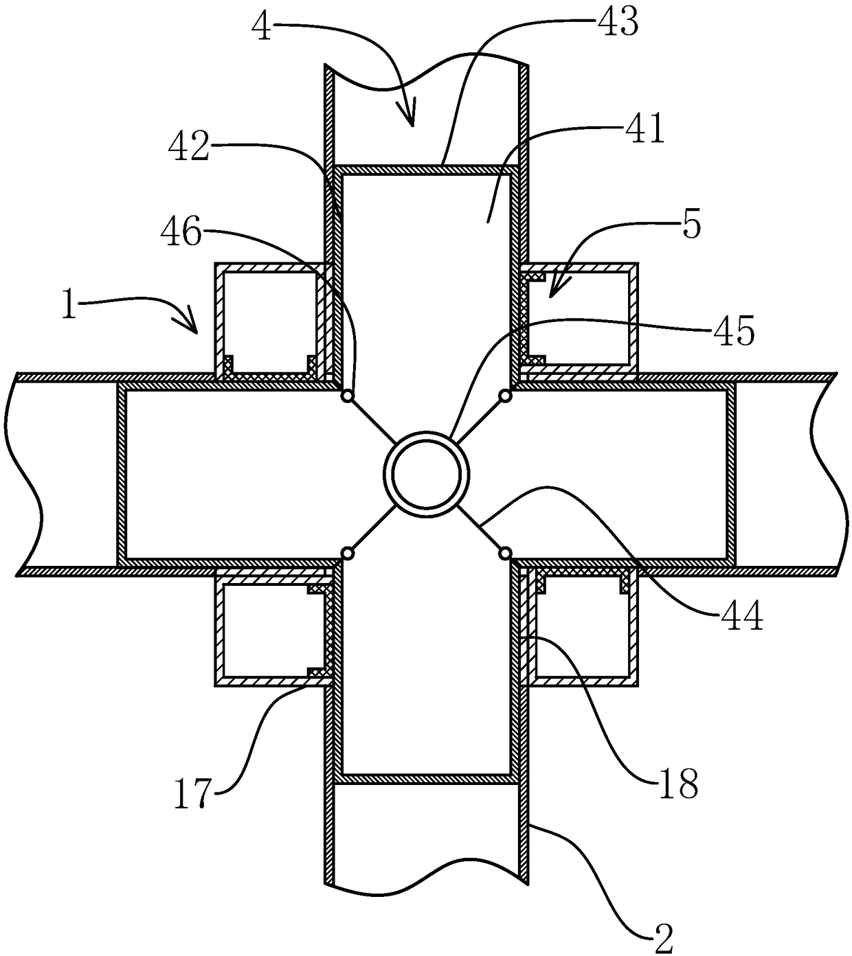
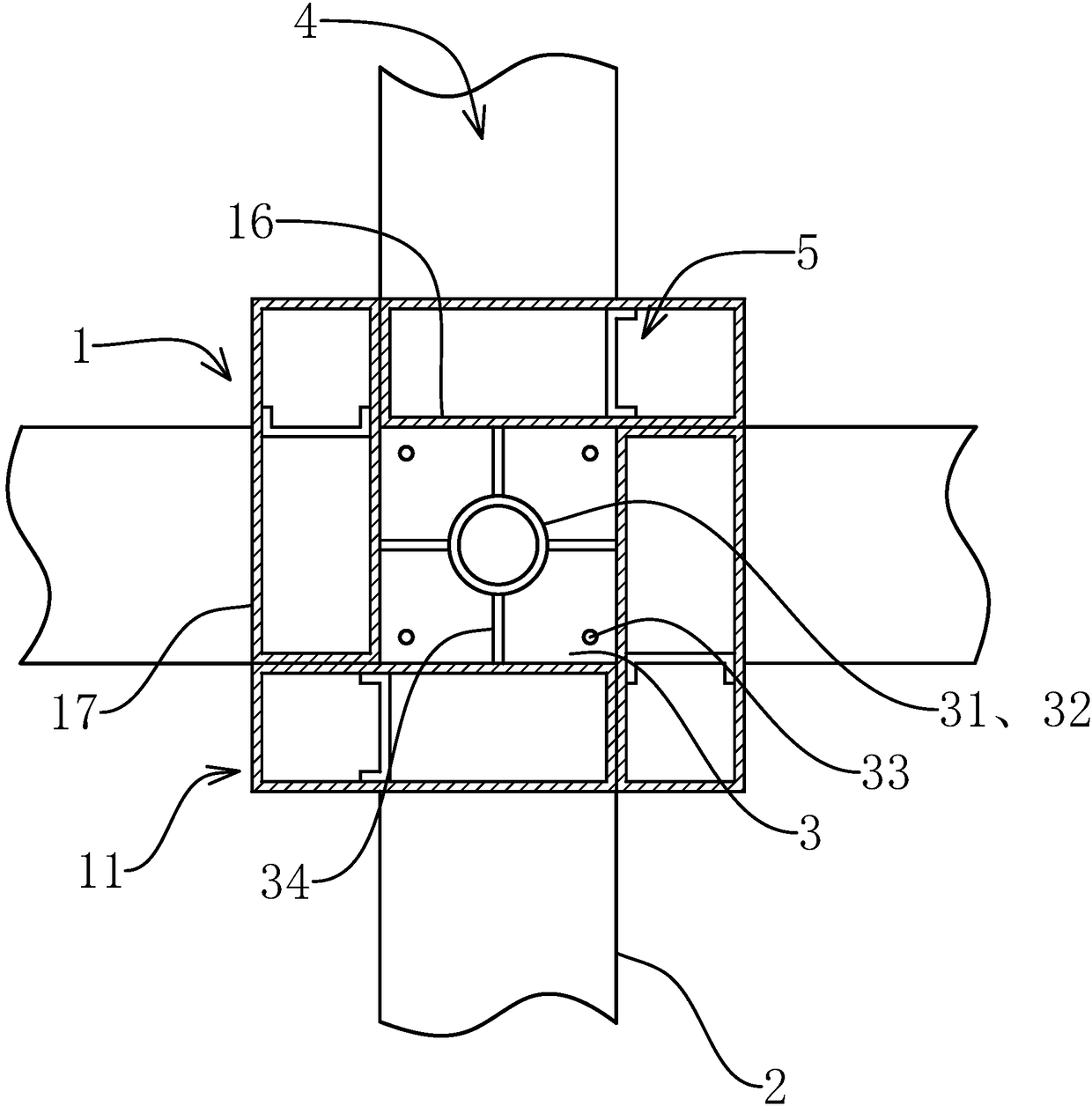
[0038] Such as Figure 1-3As shown, a square tube beam-column node of the present invention includes a vertically arranged square tube column body 1 and four horizontally arranged square tube beam bodies 2, and the column body 1 includes four outer column plates enclosing and forming a square tubular structure 17 and four inner column plates 16 enclosing to form a square tubular structure, the four inner column plates 16 are located inside the four outer column plates 17, and are respectively parallel to the four outer column plates 17, and the four inner column plates 16 are enclosed to form The grouting channel, the cylinder 1 includes four rectangular tubular enclosures 11, the enclosures 11 include inner short enclosur...


PUM


Abstract

The inventions provides a square tube beam-column joint and a construction method thereof and belongs to the field of steel structures with an aim to solve the problem that existing beam-column jointconstruction is low in efficiency and strength. The square tube beam-column joint comprises a square tube column and a beam, the column comprises four outer column plates and four inner column plates,and the inner column plates enclose to form a grouting channel; the column comprises four round tubes, each round tube comprises an inner short round plate, an outer short round plate, an inner longround plate and an outer long round plate, the outer side of the inner short round plate is adhesively fixed with the outer side of the inner long round plate of the neighboring round tube, the outerside of the outer long round plate is flushed to the outer side of the outer short round plate of the neighboring round tube to form the outer column plate, and the inner long round plate forms the inner column plate; the column further comprises an inner node plate, the periphery of the inner node plate are welded to the inner side of the inner column plate, a grouting hole is arranged in the center of the inner node plate, and each of the inner column plate and the outer column plate is provided with a running hole; the column further comprises four beam connecting tubes which penetrate therunning holes, concrete mortar is poured into the grouting channels, and ends of the beam are fixedly sleeved in the beam connecting tubes. The beam-column joint is high in strength and construction efficiency.

Description

technical field [0001] The invention belongs to the technical field of building steel structures, and relates to a square tube beam-column joint and a construction method thereof. Background technique [0002] In the steel structure buildings that are widely used at present, it is usually necessary to install the beam body on the side of the column body. The existing method generally directly connects the end of the beam body with the outer wall of the column body through connecting steel plates, which not only needs to connect multiple steel plates, but also leads to low construction efficiency. , at the same time, the connection between the steel plate and the beam and column bears a large force, and because the beam and column are hollow structures, the joint position is easy to squeeze the column and cause the column to deform, so the steel structure formed is low in strength and stable. Poor performance, affecting building safety, so it is necessary to improve. Conten...

Claims


Application Information

Patent Timeline
IPC IPC(8): E04B1/24E04B1/58
CPCE04B1/2403E04B2001/2406E04B2001/2451
Inventor 王斌辉
Owner 新昌县丽晶工业产品设计有限公司
Learn More