Eureka AIR delivers breakthrough ideas for toughest innovation challenges, trusted by R&D personnel around the world.

Thread winding and threading mechanism and method for cop latches and sewing machine

A bobbin and thread winding technology, which is applied to sewing machine components, bobbin winding in sewing machines, sewing equipment, etc., can solve problems such as low success rate, inability to wind the thread, complex structure, etc., and achieve accurate threading and easy control , the effect of simple structure

Active Publication Date: 2018-06-29
JACK SEWING MASCH CO LTD
View PDF11 Cites 9 Cited by
  • Summary
  • Abstract
  • Description
  • Claims
  • Application Information

AI Technical Summary

Problems solved by technology

Therefore, the success rate of bobbin winding and threading in this way is low, and it is also necessary to ensure that the pre-wound sutures are overlapped, otherwise, after the official winding starts, the previously pre-wound sutures will loosen and cannot be wound. Moreover, the use of manipulators to grab, wind and thread threads not only has a more complex structure, but also requires higher requirements for the control of the manipulator's winding process.

Method used


Image

  • Thread winding and threading mechanism and method for cop latches and sewing machine
  • Thread winding and threading mechanism and method for cop latches and sewing machine
  • Thread winding and threading mechanism and method for cop latches and sewing machine

Examples


Embodiment 1

[0143] The winding and threading principle of the bobbin winding and threading mechanism 50 in Embodiment 1 is as follows:

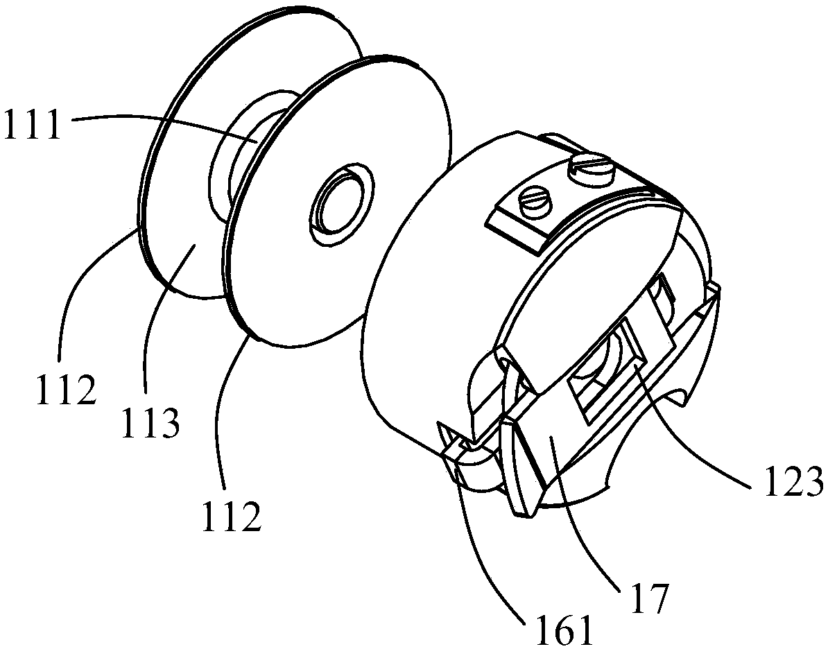
[0144] First, the first bobbin core 11 is separated from the first bobbin case 12; as Figure 16 with Figure 17 As shown, after all the remaining sutures 70 on the first bobbin core 11 are removed, the first bobbin core 11 and the first bobbin case 12 are taken off from the fixed shaft 41 by the shuttle gripping mechanism 30, and are placed on the winding shaft backwards. On the bobbin 52 , the first bobbin 11 is locked and fixed on the bobbin 52 under the action of the bobbin fixing spring 57 . Grab the shuttle linear stepping motor reverse action reset, make the hook claw 33 of grabbing the shuttle and loosen the bobbin case plate 17 of the first bobbin case 12, then the hook portion 161 of the clip bar 16 on the first bobbin case 12 does not catch the first bobbin case. The flange 112 of the bobbin core 11; the hook seat moving motor 317 rotates to...

Embodiment 2

[0149] The knife rest installation sleeve 541 is rotatably and movably supported in the main board 21, and the said winding shaft 52 is rotatably installed in the knife rest installation sleeve 541, that is: the knife rest installation sleeve 541 can be rotated and can also be moved forward and backward. move, while the bobbin 52 is only rotatable. Now, the winding drive source 51 is a winding motor fixed on the main board 21, the output end of the winding motor is fixed to the winding shaft 52; Frame installation sleeve 541 moves the knife rest driving source along the axis of the winding shaft 52. The knife rest moving driving source can be an electromagnet, a cylinder, etc., and the output end of the knife rest moving driving source is fixed with a moving plate. The mounting sleeve 541 is rotatably supported in the moving plate. The clamping drive source 53 is a clamping motor fixed on the moving plate. The output end of the clamping motor is fixed to the knife rest mountin...


PUM


Abstract

The invention provides a thread winding and threading mechanism for cop latches. The mechanism comprises a main plate with the fixed position, a winding shaft which is driven by a winding driving source to rotate and used for fixing the first cop latch, a thread clamping base which is driven by a thread clamping driving source to rotate and a shuttle grabbing hook claw which is driven by a shuttlegrabbing driving source to rotate and used for grabbing a first shuttle shell. The shuttle grabbing hook claw and the shuttle grabbing driving source are arranged on a hook claw base, the hook claw base can move in the axial direction of the first cop latch and is provided with a thread clamping gap and a gap inlet which is formed in one end of the thread clamping gap, the winding shaft and / or the thread clamping base can move in the axial direction of the first cop latch, and the winding shaft, the thread clamping base and the hook claw base can be supported by the main plate. According to the thread winding and threading mechanism for the cop latches, winding is achieved through cooperation of the winding shaft, the thread clamping base and the hook claw base, then threading is achievedaccording to a simplified manual threading track, winding and threading can be accurately conducted accordingly, and the mechanism does not need a mechanical arm and is simple in structure and easy to control.

Description

technical field [0001] The invention relates to the field of sewing machines, in particular to a bobbin winding and threading mechanism and method. [0002] The invention also relates to a sewing machine. Background technique [0003] The rotary hook of the sewing machine is equipped with a bobbin case and a bobbin. The bobbin is wound with sutures, and the amount of sutures wound on the bobbin is limited. Empty needles will destroy the fabric or a certain seam, which will cause the seam to stop halfway, and the part of the seam that has been sewn must be removed. Therefore, in actual operation, the turner will stop sewing after sewing for a period of time according to experience, then take out the bobbin in the rotary hook, and pull out all the remaining sutures on the bobbin, and then rewind the bobbin full of sutures. Putting it into the rotary hook and then continuing to sew, it takes a long time, the operation is cumbersome, and the efficiency is low, which eventually...

Claims


Application Information

Patent Timeline
IPC IPC(8): D05B59/00
CPCD05B59/00
Inventor 何贤权吴克宏蒋昌林吴善敏蔡鹏鹏
Owner JACK SEWING MASCH CO LTD
Why Eureka
Eureka Blog
Learn More