Starfish simulation robot
A robot and starfish technology, applied in the field of bionic robots, can solve the problems of low energy utilization rate in structural design, not reaching the level of practical application, and insufficient research on biological movement mechanism
- Summary
- Abstract
- Description
- Claims
- Application Information
AI Technical Summary
Problems solved by technology
Method used
Image
Examples
Embodiment 1
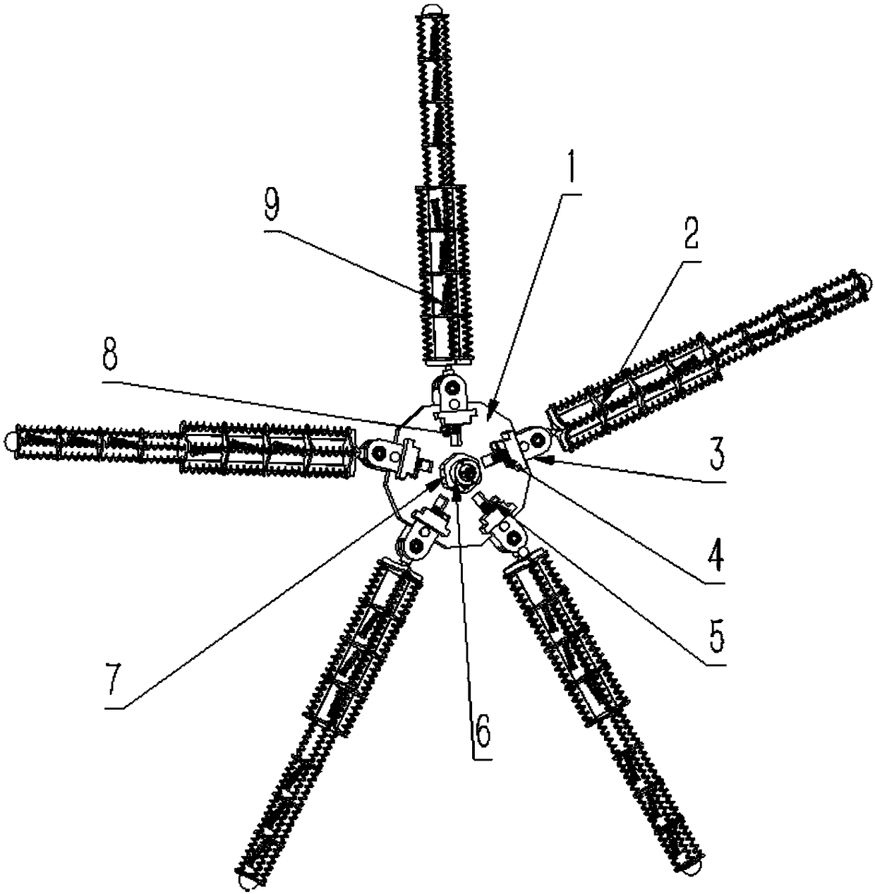
[0077] like figure 1 As shown, 1-base 2-bending leg device 3-arc swinging device 4-gear 5-servo motor 6-automatic telescopic rotating camera device 7-electrical component control box 8-fixed servo motor gland 9-tube foot device
[0078] like figure 1 Shown is the structure diagram of the starfish-like soft-rigid robot. This example includes a frame and a motion mechanism. The frame includes a base 1, an electrical component control box 7 arranged on the upper part of the center, and an automatic telescopic and rotating camera device 6. The motion mechanism includes an up and down motion mechanism, an arc swing device 3, and a bending leg mechanism 2.
[0079] The up and down movement mechanism is placed on the base 1 , including the base 1 , the gear 4 , the servo motor 5 , the fixed servo motor gland 8 , and the lifting block 47 . The lifting block 47 is a part of the base of the arc-shaped swinging device 3 , and a row of teeth is arranged on the side thereof to engage wit...
Embodiment 2
[0096] like Figure 11-20 As shown, the second embodiment has many similarities with the first embodiment. There are two main differences.
[0097] One is in the form of mechanism control of the bending leg device 3'. In this embodiment, the setting of the bending leg device 7' does not require servo motor control, but directly uses an electrically driven memory metal spring to control the bending, and makes some changes in the design of the mechanism.
[0098] The second is the design of the foot device 7'. In this embodiment, the control of the servo motor in the first drive bending section device is replaced by an electrically driven memory metal spring, and some changes are made in the design of the mechanism.
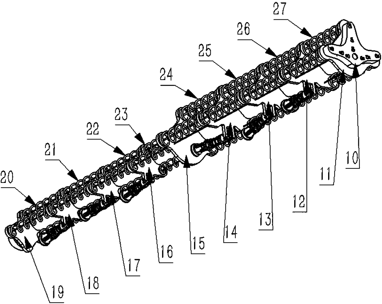
[0099] like Figure 12-13 As shown, the bending leg device 3' includes a second driving mechanism and a second bending mechanism. The second bending mechanism includes a drive mounting plate 10', an articulation connection plate 11', anterior segment intermedi...
PUM
 Abstract
Description
Claims
Application Information
 - Generate Ideas
- Intellectual Property
- Life Sciences
- Materials
- Tech Scout
- Unparalleled Data Quality
- Higher Quality Content
- 60% Fewer Hallucinations
Browse by: Latest US Patents, China's latest patents, Technical Efficacy Thesaurus, Application Domain, Technology Topic, Popular Technical Reports.
© 2025 PatSnap. All rights reserved.Legal|Privacy policy|Modern Slavery Act Transparency Statement|Sitemap|About US| Contact US: help@patsnap.com


